Six-channel color music set-top box. How to make color music on LEDs with your own hands?
And obviously
Buy wholesaleThe light-music set-top box is equipped with microphones, which allows, without connecting to a device, the sound to be added to the musical creation by coloring the color.
The greatest color effect is achieved when six channels of different-colored 220V frying lamps with a intensity of no more than 50 W per channel are connected to the skin. The skin canal has autonomous regulation.
The device can be installed in the plastic case BOX M-54P, but the kit does not come included.
Technical characteristics
additional information
Do you want to make homemade light music with your own hands? Who can help dial MK294!
The folding board is not foldable and is housed in the case, which allows it to be heated with ignition lamps of up to 300 W.
Garlands of lamps are connected using hand screw sockets.
Each of the three frequency channels (low, mid and high frequencies) has two output controls, so the set-top box allows you to simultaneously control six channels.
To control the voltage, the thyristors are pressurized.
With the help of activated microphones, the device responds to any sounds nearby. Adjustment resistors can be used to adjust the sensitivity of the skin channel depending on the specific noise and sound environment.
The set-top box is more reliable and more enjoyable than light music for home parties!
The device can be installed in the plastic case BOX M-54P, but the kit does not come included.
Statti
What is needed for folding
- Please, be kind, bookmark SUPPLEMENTARY PRODUCTS: this will help you with a new world of victorious ability to build.
Collection procedure
- All components included in the kit are mounted on another board using the soldering method.
- All permanent resistors (R30 and R31) are installed vertically on the board.
- Resistors R7, R8, R18, R19 are not installed on the board and are not included in the kit. If you are a radio amplifier, then, if necessary, you can install them to change the gain of the cascades and, therefore, change the sensitivity of the device to the signal from the microphones. The value of resistors R7, R8, R18, R19 is determined by the last step, by installing time-sensitive tuning resistors with a nominal value of 100 kOhm.
- For this purpose, resistors R7, R8, R18, R19 are not required and are not included in the device kit and are not installed on the other board.
Technical service
- The device operates at 220 V! The board must be insulated in such a way as to prevent the fraying of the wire-conducting elements. Show off the garlands of the guilty, be well insulated and do not touch bare plots.
Nutrition and types
- The set-top box does not work, what could be the problem? Nothing changes at the 12 volt outputs and the sound =(
- Zazvichay tse buvaje through polikki montazhe. Please send a clear photo of the soldered wire board on both sides. We think it's a bug all at once. Addresses: [email protected]
- 500 watts per skin channel from 6? for the entire installation?
- Drukar's mercy. Up to 50 Watt ignition lamp for the skin canal, up to 300 for the entire installation.
- I would like to improve the color music scheme. I would like one channel. It is unclear whether analog or digital, or frequency filters, in which order? very rich food
- Marvel https://site/zip/nk294.pdf
Practically at the skin radioamator-earth, and not only, it was due to take the color music console or there is fire to run in order to make listening to music more attractive in the evening or on holy days. This article is about a simple color-music console, collected on LED, which allows you to send a message to the radio broadcaster.
1. The principle of color attachments.
The work of color-musical consoles ( CMP, CMU or else HAPPY BIRTHDAY) is based on the frequency spectrum of the audio signal with further transmission by adjacent channels short, middleі high frequencies, where each channel controls its light source, the brightness of which is indicated by the sounds of the sound signal. The final result of the work of the console is the removal of color, which is indicative of the musical creation that is being created.
To select a wide range of colors and the maximum number of shades of colors in color music consoles, at least three colors are selected:

The part of the frequency spectrum of the sound signal is requested for assistance LC-і RC filters where the filter adjusts to its narrow range of frequencies and passes through itself only a certain amount of the sound range:
1
. Low pass filter(LPF) passes vibration with a frequency of up to 300 Hz and select the color of the light in red;
2
. Mid-pass filter(PSF) passes 250 - 2500 Hz and select the light color green or yellow;
3
. High frequency filter(HPF) passes at 2500 Hz and is higher, and the light color is selected blue.

Whether there are any fundamental rules for choosing the transmission range or color of the lamps, the radio amplifier can set the colors depending on the characteristics of its color, and also change the number of channels and the width of the range of frequencies according to your discretion.
2. Principle diagram of a color-music console.
Below is a diagram of a simple four-channel color music set-top box, assembled on LEDs. The set-top box consists of an input signal booster, four channels and a life block, which ensures the life of the set-top box against the changeable flow.

The audio frequency signal is applied to the contacts PC, OKі Zagalny rose X1, and through resistors R1і R2 is wasted on a replacement resistor R3, which is also a regulator of the level of the input signal Out of the middle output of the exchangeable resistor R3 sound signal through a capacitor Z 1 that resistor R4 go to the input of the front booster, based on transistors VT1і VT2. Zastosuvannya pіdsilyuvach allowed vikoristovvat prefix with any kind of sound signal.
From the output of the booster, the sound signal is sent to the upper connections of the booster resistors. R7,R10, R14, R18 What is important is to enhance the function of regulating (adjusting) the input signal directly along the skin channel, and also set the required brightness of the LEDs in the channel. From the middle mounts of tuning resistors, the sound signal goes to the inputs of four channels, each of which contributes to its own sound range. Schematically, all Wikon channels are, however, separated by RC filters.
Per channel greatest R7.
Related filter to the condenser channel C2 it misses the spectrum of the upper frequencies of the audio signal. Low and mid frequencies do not pass through the filter, the fragments of the capacitor supports at these frequencies are large.
Passing the capacitor, the high frequency signal is detected by the diode VD1 it is fed to the base of the transistor VT3. The voltage that appears at the base of the transistor is displayed by a group of blue LEDs. HL1 — HL6, included in this collector's lancet, are set on fire. And the greater the amplitude of the input signal, the stronger the transistor is, the brighter the LED will burn. To exchange the maximum flow through the LEDs, resistors are connected in series with them R8і R9. Due to the presence of these resistors, LEDs can go wrong.
Per channel middle frequency signal is supplied to the middle output of the resistor R10.
Related filter to the creation channel with a contour С3R11С4, which for low-frequency frequencies makes a significant reference, then to the base of the transistor VT4 to avoid the vibration of the mid frequencies. The collector side of the transistor has an LED on. HL7 – HL12 green color.
Per channel short frequency signal is supplied from the middle output of the resistor R18.
Filter channel creations by contour С6R19С7, which attenuates signals of mid-range and high-frequency frequencies, and thus to the base of the transistor VT6 to avoid the vibration of low frequencies. The selected channel has a LED light. HL19 – HL24 red color.
To expand the color theme, a channel has been added to the color music console yellow colori. Filter channel creations by contour R15C5 It focuses on the frequency range closer to low frequencies. The input signal to the filter comes from a resistor R14.
Live the colorful music console with steady tension 9V. The life block of the attachment is folded out of the transformer T1, diode bridge, connected to diodes VD5 – VD8, microcircuit voltage stabilizer DA1 type KREN5, resistor R22 and two oxide capacitors C8і C9.
Serious voltage, rectified by a diode bridge, smoothed by an oxide capacitor C8 and go to the voltage stabilizer KREN5. Z visnovka 3 The microcircuits stabilize the 9V voltage and supply it to the set-top box circuitry.
To remove the 9V output voltage between the negative bus of the life and output unit 2 microcircuit inclusion resistor R22. By changing the value of the support resistor, the required output voltage at the output is determined 3 microcircuits.
3. Details.
The set-top box can be used with any constant resistors with a voltage of 0.25 - 0.125 W. Below are shown the values of the resistors, which are used to determine the size of the support using color schemes:

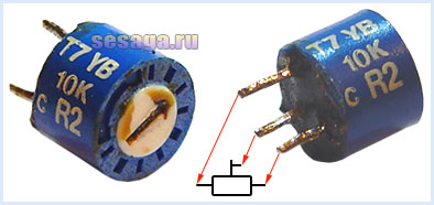
Replacement resistor R3 and adjustable resistors R7, R10, R14, R18, of any type, or suitable for the size of the circuit board. In the author's version of the design, a high-quality exchangeable resistor of the SP3-4VM type and imported adjustable resistors are used.
Fixed capacitors can be of any type and rated for an operating voltage of no lower than 16 V. If there is a problem with the addition of a capacitor C7 with a capacity of 0.3 uF, it can be connected from two connections in parallel to the capacitor. stu 0.22 µF and 0.1 µF.
Oxide capacitors C1 and C6 operate at a voltage not lower than 10 V, capacitor C9 is not lower than 16, and capacitor C8 is not lower than 25 V.

Oxide capacitors C1, C6, C8 and C9 polarity Therefore, when installing on a breadboard or a prototype board, it is necessary to ensure that the capacitors of the Radyansky production plant have a positive symbol on the case, while current manufactured and imported capacitors have a negative symbol.

Diodes VD1 – VD4 are either from the D9 series. A color scheme is applied to the body of the anode diode, which indicates the letter of the diode.

As a rectifier, collecting on diodes VD5 - VD8, a ready-made miniature diode is used, rated for a voltage of 50V and a flow of at least 200 mA.

If you replace the finished bridge with straight lines, you will have to adjust the structure of the board a little, and then you will have to insert attachments between the main board and pick up on the side of a small board.
For self-folding bridges, the diodes are taken with the same parameters as the factory settings. There are also some direct examples from the series KD105, KD106, KD208, KD209, KD221, D229, KD204, KD205, 1N4001 - 1N4007. If you choose models from the KD209 or 1N4001 – 1N4007 series, then the place can be taken directly from the side of the Drukarsky installation directly on the contact plates.
LEDs are available in yellow, red, blue and green colors. Each skin channel contains 6 pieces:

Transistors VT1 and VT2 from the KT361 series with any letter index.

Transistors VT3, VT4, VT5, VT6 from the KT502 series with any letter index.

Voltage stabilizer type KREN5A with any letter index (imported analogue 7805). If you use nine-volt KREN8A or KREN8G (imported analogue 7809), resistor R22 is not installed. Instead of the resistor on the board, a jumper is installed that connects the middle output of the microcircuit with the minus bus, and when the board is prepared, this resistor is not transferred.

To connect the set-top box to the sound signal horn, a three-pin jack connector is used. The cable is connected to the computer mouse.

The life transformer is ready-made or self-powered with a voltage of at least 5 W with a voltage on the secondary winding of 12 - 15 V with a voltage of 200 mA.
In addition to the statistics, look at the first part of the video, which shows the beginning stage of the folding color-music console
Whose first part will run out.
Yakshcho Vi have come to their senses play music on LEDs, then select the parts and be sure to check the reference data of diodes and transistors, for example. And the residual folding and adjustment of the color-music console is being created.
Good luck!
Literature:
1. I. Andrianov "Add-ons to radio receivers."
2. Radio 1990 No. 8, B. Sergeev “Simply color-musical consoles.”
3. A guide to the operation of the “Start” radio constructor.
“Color and music installations (CMU) will provide the support of musical works with light effects. Such devices improve the absorption of musical creations and significantly advance the level of their emotional and psychological influx into the individuality.
In the development of music one can see two main directions.
Pershe conveys the vitality of the harsh connection between the musical creation and his colorful accompaniment. The process of the Muziki on the stabberry male “color operator” - the people of the Music, the museum of the murmur, the vicony of the Party of the composer, and the subcubs of the composer, the abstract by Emotsiy Laws of the Analiza Mushrooms, In this case, the color-baby bathing does not turn on automatically. Obviously, regardless of the high aesthetic density of such audiovisual programs, the real drawback of such systems is their great complexity and flexibility, as well as the need for a highly qualified operator.
Another, much wider than the expansion of direct lines, representations of devices that automatically analyze a musical sound directly in the process of its interpretation for a predetermined algorithm, which changes the light flow across the spectrum and brightness in a similar manner equality. The advantage of this type is its extremely simple design and, as a result, the ease of implementation and mass repetition. However, such settings exclude the possibility of full fidelity to the character of the color scheme and the style and instead of the musical creation.
Based on this principle, a wide variety of CMU units have been successfully created - from complex stationary installations for servicing cultural and species-specific entrances to small rooms designed for a limited audience. In most cases, the end devices of the CMU produce colorful babies near the flat area. With the use of lamps, frying is practiced by placing them in adjacent shades - for the number of colors that the installation allows. Such a solution does not allow the CMU to be completely victorious and reduces the effectiveness of its emotional outpouring on people.
Most often, the terminal device of the CMU has a flat screen, on which a colorful baby is projected using electric lamps with highlighters located behind it. At the founding of vipads on the Ekrani, the instrument is able to do the title of Estrate Zmihuvannya Koloriv, in the result, the same is staggered by the bagatobarvosti at Vicoristani Vipromіnyuvachiv trookh Koloriv - the green, green so blue. In this case, the colorful baby is exposed to even greater diversity and repetition, while due to the above-mentioned effect, the hearing is affected by the sameness and repetition of the color baby. So, by placing the light cylinders in the vastness and power of the screen itself, the great world will ensure the effectiveness of the color accompaniment of music.”
I specifically mentioned this great quote from this article here, because in the 30 years since its publication, in principle, little has changed. The main focus was on the technical side of color music: analog-to-digital and digital-to-analog conversions, computer control with the help of specially developed programs, lasers and light-emitting diodes. Few can say right away that there is a greater color-music effect, which is accompanied by a “color operator.” The absolute majority of the CMU is automatic. Moreover, a lot of people have begun to not understand the very essence of color music and respect the momentary light of different colors (or even the same color!) light bulbs that are smaller in the rhythm of the music of color music itself. I want a little bit of this peace. My article is intended primarily for young people who can read and comprehend what they have read. And even better, if you want the stink and you want to work it with your own hands.
2. “Bang” the sound...
Once upon a time, all the buildings were connected to a radio broadcast line. Before it, so-called subscriber stations were connected, who created one (later - three) radio program that was broadcast by wire. The payment for the price is kop_ychan, so the guchnomovets “bubnіv” are steady. The radio voltage has become our locality ~36 to an even insignificant level. I decided to connect a light bulb to the radio broadcast line from the intestinal tract and incredulously noticed that the thread of the voltage bulb was moving in time with the sound. For me it was a surprise! I first learned that the sound can be changed to light. The brightness of the light bulb changed accordingly to the loudness of the sound. Later, when I started to immerse myself in radio technology and read all sorts of intelligent books, I learned two more speeches. First of all, the sound range consists of a range of low (LF), middle (MF) and high frequencies (HF). This had nothing to do with music color, but stemmed from the possibility of timbre control (bass and high frequency) in the power of radio receivers, electric machines and tape recorders. In another way, I learned that the Russian composer Alexander Scriabin, already at the beginning of the 20th century, wanted to embrace music in a light manner and recorded “colorful” notes in the recording of his works. Of course, Scriabin was not thinking about some kind of automatic, light-hearted support of music. We respect that only people can fully integrate into reality. I didn’t download “Prometheus” from the light guide, but this year literally struck me.
The very idea of an automatic color-coded music circuit had already been implemented (at the time I started chatting), and simple schemes had also already been started.
In its simplest form, the CMP operates immediately: the electric signal of sound frequency is located on the section of the filter --> the skin filter sees its range of frequencies in the sound range: low, mid and high --> the skin signal comes to its light bulb, the brightness of which is menu is proportionally equal to the signal from the line frequencies (Fig. 1):
Divided into frequency sub-ranges intellectually, for example: LF – from 300 Hz to 2500 Hz, MF – from 300 to 2500 Hz, HF – from 2500 Hz to 2500 Hz. Frequency filters do not produce sharp differences between ranges, which often overlap (Fig. 2), and therefore allow you to select from the three main colors (red, blue, green) any shades of colors. 
The similarity of frequency ranges to red, green and blue colors is also smart. This is the same logic: the low frequencies of the sound range are represented by the low frequencies of the light spectrum, the middle frequencies are represented by the middle frequencies, and the high frequencies are represented by the high frequencies.
The number of DMP filters can be increased by dividing the sound range into two about a greater number of frequency channels, or, for example, put the color of the sleepy spectrum on the skin note (Fig. 3): 
Small 3.
However, I do not see any possible prospects for expanding the capabilities of the CMU or aspects of their constructive complexity.
I will explain and, as far as possible, show some simple and not even the design of the CMP.
 The simplest CMP(Fig. 4) є 1:1 practical implementation of the block diagram shown in Fig. 1.
The sound signal from the speaker of the radio, recorder, tape recorder goes to the black filter. Resistor R1 serves to regulate the signal. High-pass filter – capacitor C1, mid-range filter – capacitor C2 and coil L1, low-pass filter – coil L2. Before the output of the filters, connect 2.5 V or 3.5 V light bulbs, painted in blue, green and red colors. Capacitors - any kind of permanent capacitance (except oxide ones). The bobbins are wound on metal bobbins like a sewing machine. The bobbins have an internal diameter of 65 mm, an external diameter of 21 mm, and a width of 8 mm. Coil L1 is wound on one bobbin and contains 400 turns of PEL 0.23. Spool L2 - on two bobbins, fastened with a metal bolt, with 2x300 turns of the same bobbin.
This is my first TsMP, because I connected the 5U06 booster for the school film projector KPSh-4 to the output. 3.5 V bulbs are filled with watercolors. The set-top box worked, it was good to change the brightness of the lamps in time with the changes in the LF, MF and HF sound signal. But because the primitive preparation did not give the effect of mixing colors, I did not draw up a CMP for a seemingly rounded design.
 3.1. A simple DMP on three transistors (Fig. 5) from the magazine “Yuniy Tekhnik”, 1975, No. 11 uses only three tight transistors of the P213A type (others will do, for example P4, P214-217). The transistors are included in the boost cascades behind the carbon emitter circuit, and from them they are used to enhance the entire range of frequencies. Thus, the cascade on transistor VT1 powers HF, transistor VT2 – midrange, and transistor VT3 – LF. The frequency range is affected by the simplest filters combined with RC straps. The input signal to the filter is supplied from the motor potentiometer R1, which in this case is the gain regulator that is central to all cascades. In addition, to select the strength of the skin cascade, the circuit has variable resistors R3, R5, R7. The displacement of the transistors is indicated by the values of resistors R2, R4, R6. The aim of the skin cascade is to turn on two light bulbs in parallel (6.3 x 0.28 A). The circuit is based on a constant current source with a voltage of 8-9, which is supplied from a half-wave rectifier to the diode VD1. Capacitor C1 smoothes out the pulsation of the rectified voltage. A variable voltage of 6.3 is taken from the “hot” winding of the power transformer of the device to which the set-top box is connected.
Setting up the set-top box is based on selecting the values of resistors R2, R4, R6. Depending on the input signal, their values are selected such that the voltage threads of the ice lamps light up.
I created this TsMP in a seemingly rounded design in a rectangular body. In the middle was a board with all the details. The lamps (2 pcs 6.3Vx0.28A per channel) were strengthened before the beater (a piece of cardboard covered with foil). The screen is a flat piece of corrugated plexiglass. I coated the light bulbs with a paste of ball handles, dissolved in a no-barrel nitro varnish. As a result, I ended up with a richly colored picture, which is due to the mixing of colors.

In an old photograph (small 6) the right-handed box on the table is my DMP on transistors.
3.2. CMP on several transistors (RADIO, 1990 No. 8)  This CMP is developed due to the frontal visibility of the front booster and the power supply block (Fig. 7), which makes it possible to prepare it in what appears to be a closed, autonomous structure.
I respect that the diagram does not require any special explanations. It is important to note that it migrates on the Internet from site to site, and the importance of the output transistors is to install not only a lamp, but also an LED and an electric motor for the laser DMP.
3.3. DMP on 10 transistors from the background channel  (http://shemabook.ru/)
After making a simple color music console, anyone would want to create a design that would provide greater brightness to the light lamps, sufficient to brighten a screen of significant size. The light can be created by using car lamps (12 V voltage) with a voltage of 4...6 W. An attachment works with such lamps, the diagram of which is shown in Fig. 8.
The input signal, which is taken from the dynamic head of the radio device, goes to a separate transformer T2, the secondary winding of which is connected through capacitor C1 to the sensitivity regulator - variable resistor R1. Capacitor C1 separates the low-frequency range of the console, so that it does not have, say, a signal to the background of the alternating stream (50 Hz).
From the sensitivity regulator motor, the signal goes through capacitor C2 to storage transistor VT1VT2. From the required transistor (resistor R3), the signal is supplied to three filters, which “distribute” the signal into channels. HF signals pass through capacitor C4 through filter C5R6C6R7 - MF signals through filter C7R9C8R10 - LF signals. At the output of the skin filter there is a changeable resistor, which allows you to set the required gain for this channel (R4 - HF, R7 - HF, R10 - LF). Then follows a double-stage booster with a pressurized output transistor, connected to two series-connected lamps - prepared for the skin channel in its own color: EL1 and EL2 - in blue, EL3 and EL 4 - in green, EL5 and EL6 - in red.
In addition, the set-top box has one more channel, collecting on transistors VT6, VTIO and drawing on lamps EL7 and EL8. Tse so titles channel tla. It is required so that due to the presence of an audio frequency signal at the input of the set-top box, the screen is lightly illuminated by a neutral light, which is violet.
The background channel does not have a filter center, and the gain control is a variable resistor R12. They set the brightness of the screen. Through resistor R13 the channel is connected to the background from the output transistor to the midrange channel. As a rule, this channel charges more than others. During the hour of operation of the channel, transistor VT8 is open and resistor R13 is connected to the front end. There is no voltage connected to the VT6 transistor. This transistor, as well as VT10, are closed, lamps EL7 and EL8 are extinguished.
As soon as the audio frequency signal at the input of the set-top box changes or changes completely, transistor VT8 closes, the voltage on its collector increases, resulting in a bias voltage at the base of transistor VT6. Transistors VT6 and VT10 open up, and lamps EL7, EL8 light up. The stage of opening the transistors to the background channel, therefore, the brightness of the lamps depends on the voltage due to the voltage regulation of the VT6 transistor. And yes, you can install it with a replaceable resistor R12.
To power the vicoristan set-top box, use a single-phase rectifier on diode VD1. As a result of the pulsation of the output voltage value, the filter capacitor 3Z is taken to an equal capacity.
Transistors VT1-VT6 can be the MP25, MP26 series or other pnp structures, rated at a permissible voltage between the collector and the emitter of at least 30 V and may have a high voltage transfer coefficient (or not less 30). With this same transmission coefficient, tight transistors VT7-VT10 are stuck - they may be of the P213-P216 series. As usual (T2), the output transformer is suitable for a portable transistor radio receiver, for example Alpinist. Its primary winding (high-resistance, from the middle) is used as winding II, and the secondary (low-resistance) winding is used as winding I. Another output transformer with a transmission coefficient (transformation ratio) is also used. ii) 1:7...1:10.
The life transformer T1 is ready-made or self-powered, with a voltage of at least 50 W and with a voltage on winding II of 20...24 V at a current of up to 2 A. It is not important to attach a mesh transformer for the attachment to a tube radio receiver. You can take it apart and see all the windings, including the hemorrhage. When winding the winding of the frying lamps (the changeable voltage on it is 6.3 V), the number of turns is important. Then, on top of the hemorrhage winding, wind winding II with PEV-1 1.2 wire, which requires approximately four times more turns aligned with the filament.
Fixed resistors – MLT-0.25, variable resistors – SP-1 or similar. Capacitors C1, C4-C6, C8 - MBM or others (C8 can be made from two or three parallel connections or use a capacitor with a capacity of 0.25 µF). Capacitors C2 and C7 - K50-6, SZ - K50-ZB or stacked with many parallel and series connected capacitors of lower capacity or lower voltage. For example, you can connect two capacitors with a capacity of 4000 uF at a voltage of 25 (K50-6), connecting them in series. Or take several EGC capacitors with a capacity of 2000 μF at a voltage of 20 and connect them in pairs in parallel, and turn on the pairs in series. Such a lance will be rated for a voltage of 40 V, which is entirely acceptable.
Based on the specified parameters, you can select a capacitor with a capacitance of approximately 500 µF, or simply select a rectifier for the brook (in which case you will need both diodes).
Diode (or diode) - any other than that indicated on the diagram, insurance for rectification of power lines not less than 3 A.
In Fig. 9 the mounting plate is placed on which most of the parts of the set-top box are placed. It is not at all difficult to fasten the tight transistors to the plate with metal caps; it is enough to glue them with droplets to the plate. A life transformer, a direct diode and a capacitor, which smooths out, sits either on the bottom of the case or on the outside of a small surface. Replacement resistors for life are installed on the front panel of the case, and the input socket for connecting one side to another is on the rear panel.
If the lighting lamps are to be placed in a framed housing, it is necessary to connect them to the electronic part of the set-top box behind an additional five-pin socket. However, the attachment can have a more effective appearance depending on the placement of its elements in the central body. A screen (for example, made of organic glass with a matte surface) is installed near the visor on the front side of the body, and behind the screen in the middle of the body, place the appropriate car lamps, which are located behind the visors. Same color Behind the lamps, you should place a reflector made of foil or white paper like a tin can to increase brightness.
Now about the verification and adjustment of the console. Start with a decrease in the rectified voltage at the tops of the capacitor SZ - it will be close to 26 V and drop slightly when it is turned on again, when all the lamps light up (especially when the set-top box is in operation).
The next stage is to establish the optimal mode of operation of the output transistors, which means maximum brightness of the lamps. Let's say they start from the HF channel. The base of the transistor VT7 is connected to the terminal of the transistor VT3 and connected to the negative live wire through the clamp from the serially connected stationary resistor with support 1 kOhm and the exchangeable support 3 ,3 kOhm. Solder the lanyard when the console is turned on. First, install the variable resistor motor at a position that provides maximum support, and then smoothly move it, ensuring the normal glow of lamps EL1 and EL2. If you keep an eye on the temperature of the transistor body, you are not liable to overheat, otherwise you will have to either reduce the brightness of the lamps, or install the transistor on a small radiator - a metal plate 2...3 mm thick. Having lost the main support of the lanyard, which is the highest as a result of selection, solder resistor R5 into the attachment with such or possibly a close support, and the connected base of transistor VT7 with emitter VT3 is renewed. It is possible that resistor R5 does not have a chance to be changed - its support will appear close to the support of the lanyard, which is why.
Select resistors R8 and R11 in the same way.
After this, they check the robot’s channel. When the motor of resistor R12 moves up behind the circuit, lamps EL7 and EL8 are to blame. If the smell arises from under- or over-heating, you will need to select resistor R13.
Next, an audio frequency signal with an amplitude of approximately 300...500 mV is supplied to the input of the set-top box from the dynamic head of the tape recorder, and the variable resistor motor R1 is installed at the top behind the position circuit. Change the brightness of lamps EL3, EL4 and EL7, EL8. Moreover, with increased brightness, the first and other culprits go out, and on the contrary.
At the same time, the set-top box uses variable resistors R4, R7, RIO, R12 to regulate the brightness of the high-voltage lamps, and R1 - the brightness of the screen.
 3.4. CMP on LEDs (http://radiozuk.ru/)
The description is poor both for style and for context, but I will give only the main points.
A variable resistor regulates the level of the input signal. The switch turns on the LEDs without music (Fig. 10).

A correctly chosen scheme begins to work immediately. The only thing you need to do is select R * if you need to turn on a number of LEDs in parallel. For example, the author for 4 LEDs R = 820 Ohm.
The circuit of the entire set-top box consists of 3 channels (Fig. 11), which are divided by the ratings of the filter parts. Coil L1 is a head made from an old tape recorder.
3.5. Kolyor's music - what could be simpler? (http://cxem.net/sound/light/light23.php)
the author asks to make such arguments ->

Are you a radio amateur and you have nothing to do? Do you want to solder something, but you can’t make a choice? Let's love the music of colors! We put a disco in the house and ignite it, otherwise turn on the soldering iron and solder a little. We don’t want a disco, we’ll just put the computer near the corners, let’s blink to the music.
Setting the color allows you to adjust the colors in time with the tuned melody. For starters, we’ll take a transistor, a light-emitting diode, a resistor and a 9V power supply. The sound is connected to the sound and the voltage is supplied - fig. 12.
I what mi bachimo? The LED lights up to the rhythm of the music. The ale shines brightly under the level of thickness. And here the power comes to the sub-sound frequency. In this case, filters made of capacitors and resistors can help us. The stench lets through the singing frequency, and comes out when the light is too low for the singing sounds.  The diagram (Fig. 13) shows the example of simple music in color. Ale is just a small prefix with a slight brightness. It consists of three channels and power supply. The sound is supplied from the line output or low-frequency booster to the transformer required for galvanic isolation. When a compact hemstone approaches, a sound signal is sent to the secondary winding. You can do without it, as long as the input signal has enough light supply to burn off the LEDs. Resistors R4-R6 regulate the lighting of the LEDs. Then there are filters, some adjustments to the frequency transmission. Low-frequency – transmits signals with a frequency of up to 300 Hz (red LED), mid-frequency – 300-6000 Hz (blue), high-frequency – 6000 Hz (green). Transistors can be used practically in any n-p-n structure with a transmission coefficient of at least 50, shorter or larger, for example the same KT3102 or KT315.
You have chosen a reliable, miraculously working musical device, but why doesn’t it work? Let's modernize yogo!
 Let's get this out of the way. Greater brightness. For those who are vikors, use a 12-volt frying lamp. A thyristor (Fig. 14) and a live device from a transformer are added to the circuit. A thyristor is a cerated diode that allows cerated voltages to be applied to weak signals. When passing through a new stationary stream, the voltage is lost from the open source without a signal that controls it; with a changeable stream, the operating principle is similar to a transistor. There is an anode, a cathode - like a diode, and an additional electrode that controls it. If you want to achieve proper attention, you will need to use the control circuit for the heating lamps.
A sound signal is generated by the low-frequency booster with a pressure of 1-2 watts. Thyristors are practically rated for lamps, 12-volt automobile lamps. The transformer is responsible for supplying sufficient power (1.5-5 amperes) to the lamps (Fig. 15).  If you have enough voltage to work with, then the best option would be to use 220 volt lighting lamps. This time you won’t need a mesh transformer, but the sound quality will be better for the protection of the sound. In this case, everything is carefully insulated and placed in a reliable housing.
 Now let's start with background switching. Turn back to the main channels: when there is no sound, the LED lights up steadily, sound is heard - the LED goes off (Fig. 16). You can create one background background channel or one with adjacent sound filters and connect it behind the front circuit.
The addition circuit has a resistor (R2) for the constant voltage of the transistor. Therefore, the light can easily pass through the LED, and if the sound signal is given, the transistor will turn off, and the LED will go out.
 Replace the transformer with a transistor booster (Fig. 17).
The sound noise is added to the additional microphone. Dodamo yogo to the front diagram. Now music color is responsive to all unnecessary sounds, including rosemova.
 The circuit (Fig. 18) has the butt of a two-stage microphone booster. Resistor R1 is necessary for maintaining the microphone, R2 R6 is for setting bias, R4 is for adjusting sensitivity. Capacitors C1-C3 allow the sound signal to pass through and do not allow a steady stream to pass through. The microphone is an electric one. If the circuit is used simply as a booster, then R1 and the microphone are removed, the sound signal is sent to C1 and minus life. The part numbers are not critical; particular accuracy is not important here. Don't give in to the smut, and everything will work out for you.
Scheme Fig. 15 There is also a “transition” input from transistor DMPs to thyristor ones.
Thyristor TsMP allow vikorystuvat as a result of the lamp's tension!
I would like to respect that there are thyristor CMP circuits, where fluorescent and pulsed lamps are installed, otherwise I will not direct them.
 In Fig. 19 shows a diagram of the most primitive color music installation for three channels. This CMU includes the simplest passive filters on RC elements, the signals from the outputs of which control thyristor switches. Viprominyuvachi live without middle N! in line 220 st.
At the top of the circuit is a low-pass filter, which is adjusted to a frequency of 100...200 Hz, below the circuit is a mid-range black filter (200...6000 Hz), and at the bottom is a high-pass filter (6000...7000 Hz). The LF, MF and HF channels are represented by lamps of red, green and blue colors. Since this circuit does not interfere with the front booster, the input signal has an amplitude of 0.8...2 Art. The strength of the signal is regulated by an additional resistor R1. Resistors R2, R3. R4 is intended for regulating the equal signal in the skin channel of the skin.
The TP1 transformer is mounted on a Ш16x24 core made of transformer steel. Winding I contains 60 turns, PEL 0.51. winding II - 100 turns PEL 0.51. Any other small-sized transformer (for example, such as transistor receivers) can be used because the ratio of turns in the windings is close to 1:2. Thyristors must be installed on thermal radiators, since the total intensity of the lamps per channel exceeds 200 W.
The presented 3-channel CMU is very simple to prepare, but there are few shortcomings. This, firstly, is a great necessary input to the signal, and, secondly, a small input input, and thirdly, the sharp flashing of the lamps, the impact of the lack of compression and the primitiveness of the filters, which will stagnate.
 Small 20 – this old photograph shows the CMP (visible in color), as I soldered the induced circuit around 1981. The source of the signal is a Dnipro-12N tape recorder, the output optical device is a square screen, in which the light-colored elements of the vikoristan are two mutually perpendicular to a ball of thin hollow glass tubes.
It’s true, we didn’t have the Internet at that time, and I took the diagram from the brochure “To Help the Radioamator,” VIP. 87, S. Sorokin, Volume of the Central Medical University “Harmony”.
 In Fig. 21 shows a diagram of a similar simple color-musal attachment on thyristors D1-DZ. There are three colors and one background channel. The life of the attachment operates in conjunction with a changeable source with a voltage of 220 behind the help of a rectifier mounted on diodes D4-D7 behind a bridge circuit. The minus wire of the rectifier connections to the cathodes of all thyristors, and the positive wire through the heating lamps L1, L2, L3 of the connections to the anodes of the thyristors. The intensity of the lamps turned on near the skin canal may exceed 300 W. The background lamp L4 is connected in parallel to the thyristor D2.
From the ULF output of the primary device (radio, electrophone) - the sound coil of the dynamic head - the low-frequency signal goes to the Gn1 socket and the variable resistor R1. The low-frequency voltage of this motor resistor is supplied to winding I of transformer Tr1. The secondary winding of the second transformer is connected to the input of all filters of the three channels. The exchangeable resistor R1 is used to adjust the level of the signal at the filter input. The need for this resistor is because when the signal is high, lamps L1-L3 switch on and off at the same time, in time with changing intensity. In this case, the change in tone does not affect the operation of the lamps. Here are signs of incompleteness of the section filters. You can often combat this shortcoming with the help of an additional resistor R1, which allows you to ensure more precise switching on and turning on of the lamps of adjacent channels.
Moving the transformer Tr1 will ensure the reliability of the thyristors D1-D3. Dink for the tsoye naprog on the secondary winding of the transformer, Tobto on the input FILTRIV, guilty of Boti Blizko 2-3 V. At the same time of the mug-magnitophone (signs, primary), the Nizhchoy vid zyago zyago zyago. In addition, the transformer disconnects the alternating line from the tape recorder, which operates the CMP, which is necessary for upgrading safety equipment.
Filter C1R3 passes high frequencies, weakening the lower and middle frequencies. The lamp for the higher frequency channel (L1) is set to blue. Filter R4С2С3 passes mid frequencies, weakening lower and higher frequencies. I found that the R4R6С4 filter passes the lower frequencies, weakening the upper and middle frequencies. In the channels of mid and low frequencies, lamps L2, L3 are painted in green and red colors.
Use the prefix in this way. As long as there is no signal, all thyristors are closed and the lighting lamps L1, L3 in the high and low frequency channels do not light up. The mid-frequency channel lights up randomly (all voltage from the output of the rectifier is divided equally between the lamps of green and yellow colors). If a low-frequency signal appears at the output of the filter channel and its value is sufficient to activate the thyristor D2, the background lamp L4 will go out (it will appear short-circuited with the active thyristor), and the lamp L2 will light up with increased heat. Apparently, lamps L1 and L3 will light only when the voltages at the filter outputs of the high and low frequency channels become sufficient to open thyristors D1 and D3.
It should be noted that the thyristor opens only in the positive direction of the low-frequency signal and closes in the direction of the voltage change.
When the set-top box is prepared, it is possible to install fixed resistors MLT-1 or MLT-0.5, a variable resistor R1-draught of any type; Fixed capacitors MBM or other operating voltages are not lower than 400 V. Transformer Tr1 with viconnium core Ш 12Х12. Primary winding I has 210 turns of PEL-1 0.2, winding II has 3200 turns of PEL-1 0.09.
The KU201K thyristor can be replaced with 2U201K, 2U201L, KU201L, 2U201Zh and the like. The rectifier can operate with diodes (D4-D7) D243A, D245A, D246A, which without additional heat transfer can provide a flow rate of approximately 5A.
The design of the console can be very different. Protein facilities can be reduced to the development of safety technology, since there is also direct contact from the edge N! 220 V. Obviously, reliable insulation of the circuit board with diodes and trinistors is ensured. The remaining traces are placed under the nut on the additional heat dissipation, in a container in which you can place brass or duralumin alloys 3-4 mm in size 50 x 150 mm. Installation of heat dissipation from thyristors and other parts is carried out on a board with getinax or 3-4 mm textolite. As soon as the attachment is assembled from the knowledge of checking and reference parts and ensuring correct installation, it immediately begins to work. Having placed the handle of the variable resistor R1 in the lowest position behind the circuit diagram, connect a voltage of 220 V and supply some kind of music program to the input of the set-top box from the output of the receiver, electrophone or tape recorder. Then, by increasing the voltage at the input of the low-frequency filters with resistor R1, the set-top box requires stable operation and the best possible combination of colors on the screen. Screens can be of any design. These radio amplifiers form screens similar to decorative table lamps or spotlights installed at different ends of the room, and direct the light from them to the middle of the wall.
4.2. Kolyorova music (RADIO, 1972, No. 4)
Material from a special PAPER archive (scanned on 01/17/2013)
For this circuit, I collected my DMP on KU201L thyristors from 1979 Roci. The set-top box was designed for 12 V car light bulbs. I don’t remember why she didn’t give any final looks. 
Small 22.


The device implements the “fire that runs” effect, but the frequency of the multivibrator depends on the magnitude of the sound signal that is supplied to the input of the device. Of course, the word “colorful” in the title of the article is not correct. It is no less true that the device allows you to realize a similar effect when you change not only the fluidity of the “fires that run”, but also the direct “run” in relation to the intensity of the sound signal.
In my opinion, this device itself needs to be installed in the front design.
My version of the extension is shown in Fig. 32: 
6. Lamp CMP
6.1. RADIO, 1965 No. 10 
The DMP on the lamps allows you to remove the secondary frequency power of the filter, because The circuit transfers the design of the device and the installation with a filter. This type of filter, based on RC elements, is easier to prepare and regulate. The terminal cascades at the skin channel are collected behind the circuit from the ignited anode.
The mode of operation of the cascade of communications is such that, as long as there is no signal on the grid of the lamp that controls it, the anode flow is very small and does not fry the garland lamps. The anode strut is adjusted using replaceable supports R17, R18, R19.
The end cascades are filled with rectified voltage after the signal is amplified by other cascades.
The signal is rectified by other triodes of lamps L2, L3, L4 with the LED turned on. The ceramic grids of the end cascade lamps drain the excess positive voltage as the lamps are energized.
Potentiometers R4, R9, R14 at the input of other booster cascades regulate the strength of the skin channel. With the help of potentiometer R1, the brightness of the light of all garlands is set. The dimensions of the extension are 180x150x260 mm.
Radio tubes should be replaced with the following ones: 12АХ7 – 6Н2П, 6CL6 – 6П9, 6П18П, 5Y3 – 5Ц3С.
6.2. Color music installation, A. Aristov, metro station Pervouralsk (“UT for clever hands”, 1981 No. 4)
Material from a special PAPER archive (scanned on 01/18/2013)

It’s simple, but it’s good to install a color scheme (TsMU) so we can work on thyratrons.
The thyratron has a high (tens of megaohms) input power and high sensitivity to input signals. Therefore, the input signal is supplied without further amplification. Transformer Tr1 moves the input voltage 5-8 times and completely isolates the input of the installation from the lifeline. Then, through the sensitivity control R9, the signal is sent to a simple RC filter: HF - C1R1R2, MF - C2C3R5R6, LF - R10C4 and, as before, is divided into three channels. After filtering, the ceramic signals go to the ceramic grids (leg 1) of the thyratrons. A negative bias voltage is applied to the main legs through resistors R3, R7, R11, which is regulated by variable resistors R4, R8, R12. The RC filter, based on the high support of the thyratron, works more efficiently, is stable and does not require adjustment. The installation itself creates a picture on the screen that attracts radio amators. Near Pervouralsk, over a hundred people were killed.
In the anode lamps of thyratrons, the primary lighting lamps are switched on at 220 V. The intensity of unpaired lamps (H1, H3, H5) is approximately 2.5 times greater than the intensity of paired lamps. If the channel is not receiving a signal and the thyratron is closed, the paired and unpaired lamps are turned on sequentially, the paired lamp glows when hot, and the unpaired lamp glows with ice. When the input signal appears, the thyratron opens and briefly short-circuits the paired lamp. There the lamp goes out, and the unpaired lamp glows once again. This scheme makes it possible not to introduce a special background signal channel, and also to increase the service life of the thyratron several times. It remains to be explained that in our circuit the lamps are constantly heated. If it is cooled down to room temperature, then their operation will change a number of times, and the same number of times the rapid discharge of the stream will increase at the moment the thyratron is turned on.
The anodes of thyratrons are powered through a rectifier on diodes V6-V9. The frying lancets are located in the secondary winding of the T2 incandescent transformer. From this winding through a rectifier with sub-voltage voltages on diodes V4, V5, thyratron displacement lancets are installed
Zіbraty TsMU is best on the textolite panel of the car 2-4 mm. The design and dimensions are limited to obvious details, so we do not provide descriptions of them. Changeable resistors can operate at 15-68 kOhm. The D9Zh diode can be replaced with either low-voltage diodes, rated for a voltage of at least 20 V, KD209A - KD209 or KD105 diodes with any letter index, D226, D7Zh. Lighting lamps of 40 and 15 W. It is not recommended to increase the intensity of the lamps. Lamp H1 can be coated with red nitrofarba, N3 with yellow, H5 with green, Rash with blue or violet. Transformers can be used as Record-311 radio (output and power). Output transformer T1 (wall Sh16x18) has been rebuilt. One of the windings (II) is saved (2800 turns of PEL-0.12 dart), instead of the other (I) 400 turns of PEL-0.33 dart are wound. Between the windings you need to place a number of balls of varnished cloth. This insulation ensures safety. Vikoristani power transformer without reworking. The windings are on magnetic conductors Ш21х26. Winding I contains 1250 turns of PEL-0.29, winding II - 40 turns of PEL-0.9. You can use other transformers with similar parameters.
There is no need to install the installation without any damage. If the bias regulator is installed on the right side of the position circuit, thereby removing the bias voltage, the thyratron opens up and turns on the light lamp to illuminate the signal. This allows you to check the effectiveness of the channel. Controls for channel sensitivity and channel sensitivity controls. But we need to remember that an extreme increase in sensitivity will negatively affect stability.
7. Output optical devices of the CMP.
As practice shows, the great effect of color-coordinated music can be achieved not so much with the complicated circuitry of the set-top box, but with a well-thought-out, original design of the VOU.
Literature has had its chain broken more than once (div. pp. 5.2, 5.4, 5.6).
7.1. Obviously, the simplest option is to choose a wall or wall screen, where to direct the light flow of powered thyristor-type generators of the CMP.
7.2. The other option is more labor-intensive, but more varied, and therefore more effective. This HEU is made in the form of a box, the front wall of which is a screen, made from transparent material. The main consideration in this case is the light-colored material and the placement of the lamps behind the screen. Vikorist is used for both transistor and thyristor DMPs.
7.3. The most valuable ones are the original designs, which implement the principle of “volume” of the color pattern.
Here you can see a group of HEU, in which the “volume” is realized due to the originality of the design (not flat), the distribution and the special placement of the lamps. Ale such HEU are static.
Before the other group, I would like to mention bi VOUs, in which “volubility” and pseudo-dynamics of the color picture are realized. This is achieved by the effect of “fires that run”, which is combined with the “classical” CMP.
The third group consists of HEU, whose “volume” is combined with real dynamics. Such VOUs may cause stencils, lenses, or other objects that are visible or non-transparent to crumble, or may become light-colored and change their shape during the collapse process.
PUT IT ON
1. RADIO, 1971 No. 2 – replacement of lamps at the output of the CMP by installing electromagnets to control light filters that block the steady flow of light. 
2. RADIO, 1975 No. 8 – collection of materials 
3. RADIO, 1976, No. 4 – colorful music lamp 
4. RADIO, 1978 No. 5 – collection of materials 
In the author's designs there are a variety of different ideas for creating HEU for the CMP: in the form of a cubic stencil that wraps in the middle of the cubic screen (Fig. below Zliv, B. Galiev, R. Galyavin, TsMU "Yalki" n") to vikoristannya zvolozhuvacha povіtrya (Fig. bottom right) . I tried to search on the Internet for designs of original HEU, but there were even disappointments: same diversity, no innovative ideas, no imagination.
There is no hope of practical implementation of what has long been envisioned.
“It’s crazy, girls...”, as the great schemer said.

I’m still smart enough to call devices another type of CMP - color-music consoles, thereby emphasizing their independence from the subjective perception of music.
The microprocessor also needs to be programmed.
With a bright part, Scriabin's musical poem "Prometheus" was first celebrated on May 20, 1915 at New York's Carnegie Holly by the Orchestra of the Russian Symphony Partnership under the direction of Modest Altshuler. For this premiere, Altshuler built a new light-colored tool for engineer Preston Millar, which he named chromola. chromola); The new light party faced numerous problems and was coldly criticized.
TsMP - color music devices - that's what I call light devices automatic music support.
Transistors of such CMPs act as power elements in lanyards that control variable-voltage elements.
The thyristors of such CMPs are power elements in the lanyards that control the power elements.
Schemes of these CMPs “move” from site to site. I sold these consoles if we didn’t even know about the Internet.
If L4 is taken at two levels of less pressure, lower than L2, then the presence of the L4 signal will light up, practically, when it is fully heated, and at the maximum signal, for example, L2.
OOU is an output optical device.


Applications for accompanying musical phonograms with color effects on a six-channel (2x3) RGB strip.
It comes with a board and a set of components, including programming a microcontroller, for self-assembly of the device.
Technical characteristics:
Input voltage: DC 9...24 V;
Living strums lie down under pressure (potency R G B light lines);
Maximum flow of the collector of the skin power transistor (TIP122): 5 A;
Quiet flow: 30 mA;
Number of output channels: 6 pcs.;
Overall dimensions of the hand plate: 67 x 53 mm.
Description of the circuits:
A 9-24 DC power supply plug is connected to connector J1, in line with the RGB stripe, LED D2 signals the supply of power.
A 3.5mm Jack plug is connected to connector J2, which must be connected to any sound-generating device, or to the output of a low-frequency booster.
Before outputs P1, P2, one RGB LED strip 12/24 V is connected, as shown in the diagrams, or set to dry conditions
color channels (MF, LF, HF) Using an additional adjustable resistor R5, we set the level of the input sound signal, which is significant the brightness of the LED strip.
Button SW2 "Fadespeed" One by one press changes the fade speed of the channels due to strong peak.
Depending on the nature of the music, there may be a need to reduce the visual impact.
Press the SW2 button for more than 3 seconds and change the robot mode (standard, aggressive, aggressive x2).
The SW1 Runlight button once pressed changes the mode of the device in a quiet state (lights to run, smooth lighting,
vimkneno). After washing, when the device is first warmed up, the fire mode is set to run.
Pressing the SW1 button for more than 3 seconds saves fine adjustments (fluidity, quiet mode, robot mode).
Pressing two “Runlight” and “Fadespeed” buttons at once for more than 3 seconds will bring up the initial settings.
ATMega 8 microcontroller firmware update
Through the J3 (SPI) connector, not connected to the ATMega 8 microcontroller, you can change the current program, which can be downloaded from the site: http://lightportal.at.ua
Pereyshovshi for poslannyami: Catalog of articles / Collection of music / Lichtorgel - international music.
There you will find various updates and output codes for changing programs yourself.
For programming you can use Vikory
Four-channel color-musical device. radio designer (042)
In addition to the design option for a three-channel device on light-emitting diodes (option No. 015), the circuit looks like a multi-channel color-music device (set-top box) on triacs. Currently on the market of light fixtures there is a wide selection of frying lamps with color glass and filters of different colors, lamps with colored heat-resistant coatings of different shapes and thickness, but this set is not equipped with lamps. The main principle when choosing a circuit was maximum electrical safety for the device during the hour of operation. There is a lot of literature on this topic and circuits on the Internet, and most of the details of the circuits of the consoles on the lamps are galvanic coupling from a 220 volt circuit or the decoupling of the viconan on transformers, so it is necessary to construct a circuit that is more bulky and less carefree. Looking at this, the device’s furnishings are made from a solid hand-made board made of foil fiberglass, and not on a breadboard bakelite board, as in option No. 015. Let's look at the diagram and arrange it. The circuit consists of a variable resistor R1, which regulates the level of the input signal. Then the signal goes to several channels that are similar to one another, which are varied only by the parameters of capacitors C1 - C8, and then become concentrated in the active filters of the skin channels. The filter, which consists of capacitors with a small capacity, transmits a larger high-frequency spectrum to the signal, and the lamp channel is painted with a blue or violet color, and the channel with a maximum capacity of capacitors is distributed to the low part of the spectrum of lamps and whose channel is to be filled with red color. Other main colors occupy a similar place by analogy with the development of colors in the merry. The circuit has a sufficient amplification reserve that allows you to process low-level signals; it is necessary to supply a signal from the linear outputs of the equipment to the input of the set-top box. If this is not possible, change the output to your headphones or external speaker to the audio signal. Let's look at the circuit diagram on the first (blue) channel: the signal from R1 goes to a variable resistor equal to the signal from the first channel R2. This is through R6 to the active filter capacitor C1 C2. Through C2, the high-frequency spectrum signal goes to input 6 (9,13,2) of one of the four operational boosters (OP) DA1.1 microcircuits LM324. Resistor R14 (15,16,17) sets the operating mode of the op-amp, capacitor C1 closes the feedback loop of the active filter. At output 7 (8,14,1) the signal is amplified through capacitor C10 (11,12,13) and resistor R21 (23,25,27) goes to transistor switch VT1 (2,3,4), the role of which
The KT315 transistor is installed. Bias resistors R28 (29,30,31) ensure that the transistor is closed depending on the signal from its input. Resistors R20 (22,24,26) are used to interconnect the core of the ceramic LED optocoupler MOS3021 (you can use any optocoupler of the MOS30xx series, but without a “circuit for seeing the transition through 0”, such as MOS302x, 303x, 305x). In the remaining number, the control line is located near the marking. When a suitable signal is received at the input of the transistor, the current from the positive side of the life through resistor R20 (22,24,26) flows through the optocoupler LED. As a result of the light bias of the LED, the light-sensitive dinistor of the optocoupler is activated, through the flow-intermitting resistor R32 (33,34,35) the lance between the ceramic electrode of the triac VS1 (2,3,4) and a node A2, the triac opens and the lamp lights up. In line with the signal at the input of the transistor, keep the stage of the triac and, apparently, the brightness of the lamp that burns out. The device has VT137 (138) triacs (the numbers in the markings indicate the permissible voltage between the anodes of the triac). The maximum permissible flow of these triacs is 8 (12) amperes, which allows the lamps to stand on one channel with an incandescent power of up to 1.5/2.3 kW, which also entails the stagnation of radiators for heat dissipation of the triacs. The specificity of the circuits allows you to install one radiator on all triacs, but for safety it is necessary to secure the triacs to the radiators or one separate radiator through special insulating gaskets and an insulating screw on the edge captive bushings that can be pulled out of a faulty computer power supply. If the lamp intensity is less than 200 W per channel, the radiator does not need to be installed. As a light source for fire safety, it is important to prepare ready-made lamps with frying lamps. To power the device, use a constant voltage of 9-12 volts, carefully adjusting the polarity. The Zabozhnik protects the device and the measure from a short circuit. When using lamps with intensity up to 100W per channel, the maximum output is 2 amperes, it is obviously sufficient to use a 2-3A supply. When using 200 watt lamps, the heater is responsible for 4-5A and more when using dim lamps. In this case, it will be necessary to strengthen the copper tracks from the terminal block to the anodes of the triacs with additional jumpers or solder the bare copper tracks to the other tracks. Before connecting the device, install dry insulating covers on the heater and the semi-storage. When turned on until the adjustment hour, make sure that the board is on an insulating stand without any third-party electrically conductive objects near the board area. Remember that circuit elements connected to the circuit (sistors, 4 and 6 optocouplers, resistors R32-R35, lamps, C15-C22) are subject to dangerous voltage!
refurbishment of radio elements 042
1. Microcircuit LM324,
2. Socket for DIP14 microcircuits,
3. Drukovana board,
4. Changeable resistors (10k - 200k) (5 pcs.),
5. Plastic handles for exchangeable resistors (5 pcs.),
6. Terminal blocks RSV x2 (7 pcs.),
7. Zapobizhnik 3A/4A (2 pcs.),
8. Utrimuvach zabozhnik (“at the fee”, 2 elements),
9. Transistors KT315 (4 pcs.),
10. Optocouplers MOS3021 (4 pcs.),
11. Triac VT137 (138) (4 pcs.),
12. Constant resistors:
R6, R7, R8, R9 - 10k (Kch/Ch/Or) (4 pcs.),
R10,R11,R12,R13,R21,R23,R25,R27-4.7k (F/F/Kr)(8 pcs.),
R14,R15,R16,R17 - 1M (Kh/H/Green) (4 pcs.),
R18, R19, R28, R29, R30, R31 - 100k (Kch/Ch/F) (6 pcs.),


