Filters for acoustic stoppers 3 empty. Filter. Vіdsіkayuchi statements. Magazine "Avtozvuk". Other living schemes
Irina Aldoshina
Date of first publication:
lute 2009Separate filters in acoustic systems.
Almost all modern high-acoustic acoustic systems are rich in sulfur, which consists of a number of components that work in their own frequency range. This is due to the fact that it is practically impossible to create a dynamic generator that would ensure propagation in a wide range of frequencies with little interference (including intermodulation, as well as transient, nonlinear, etc.). ) and a broad characteristic of straightness. Therefore, in acoustic systems (both professional and everyday), a number of speakers are used (low-frequency, mid-frequency, high-frequency, and some super-high-frequency), and to distribute the energy of the sound signal between them, turn on the electrical Avoid separation.
The infusion of sectional filters into shaping the characteristics of acoustic systems at the front was underestimated: it was assigned the role of attenuating the signal along the operating frequency line of the speakers. However, the development of technology for acoustic systems in the Hi-Fi category has changed the view on the role of separation filters in acoustic systems and on the methodology for their design. Numerical theoretical and experimental work, dedicated to the use of sectional filters for the correction of the characteristics of the subjective and shaping of the objective and subjective characteristics of acoustic systems, has focused on the importance of sectional filters of other components of acoustic systems, with the help of which it is possible to synthesize many necessary electroacoustic characteristics and achieve significant progress in the assured natural sound.
First of all, we move on to the analysis of different types of filters that are used in acoustic systems, and the methods of their development, based on the selected basic parameters of the filters.
Filter options
Filter It is called a device that lets through spectral regions in the signal and does not let through (which attenuates) others. The filter can be implemented in analog circuits (passive and active filters), as well as implemented in software or in a digital device (digital filters).
Current acoustic systems have both passive and active filters (crossovers). The first ones turn on after the initial boost to the skin canal, the others turn on before the boost. The external switching circuit is shown in Fig. 1. Active filters may have a low priority over passive filters, their fragments are much easier to recycle, can be implemented in a variety of ways, they require daily effort, etc. p align="justify"> Methods for designing active filters are widely covered in specialized literature, so here we focus only on methods for designing passive filters, which are widely used in modern acoustic systems.

The main parameters that indicate the power of filters are:
- smuga pass- frequency range, which filter allows the signal to pass through;
- Smuga trimmed- frequency range, de-filtering will suppress the signal;
- Frequency immediately f cf - frequency, where the signal is weakened by 3 dB of the absolute average level of smooth transmission.
Based on the nature of the smoky blending, the transmission and smudging of the filters, they are divided into four main types.
Low Pass Filter(LPF) passes low-frequency parts of the spectrum of the signal (from zero to frequency immediately) and suppresses high-frequency ones. Used for low-frequency speakers. The shape of the frequency response is shown in Fig. 2.
High Pass Filter(HPF) passes high-frequency warehouses (as the frequency is higher) and suppresses low frequencies. Set up for high-frequency speakers. The shape of the frequency response is shown in Fig. 2.
Black filters(PF) pass songs of different frequencies (in f Wed1 to fср2) and suppress the lower and upper frequencies. Set up for mid-range speakers, fig. 2.

It's the same rezector filters, which are a combination of low-pass and high-pass filters. The stench bends the spectral warehouse signal of a singing mixture of frequencies and passes through in other areas. Stop the inputs in acoustic systems to detect frequent peaks and dips in the frequency response.
In addition, the skin from over-inflated filters is characterized by the following parameters: the steepness of the frequency response decline during the transition from transmission to dimming, unevenness in the transmission and dimming mixture, resonant frequency and quality factor (Q). Depending on the structure of the filter and the number of elements in each one, the difference in the steepness of the frequency response decline can be ensured. In acoustic systems, filters with roll-off rates of 12 dB/oct, 18 dB/oct and 24 dB/oct are used (Fig. 3), which are obviously called filters of another, third and fourth order.

The simplest structure of a low-pass LC filter of a different order is shown in Fig. 4. It includes the following elements: inductance L, the reactive element of which is directly proportional to the frequency (XL = 2πfL), and capacitance C, the reactive element of which is proportional to the frequency (XC = 1/2πfC). This is shown in Fig. 4a lance passes low frequencies (inductance L is small at low frequencies) and ensures attenuation of high frequencies. The high-pass filter has a gate structure (Fig. 4b) and, obviously, passes high frequencies and blocks out low ones.

The type of frequency response of high-pass filters is of a different order for different values of the quality factor readings in Fig. 5. The resonant frequency of such a filter is calculated as f=1/(LC)1/2, and the quality factor as Q = [(R2 C)/L]1/2.
3 fig. 5 it can be seen that changing the value of the quality factor changes the nature of the frequency response decay from smooth (at Q = 0.707) to a decline with a rise at the resonance frequency (Q = 1).
In the case of those who mathematically described the transfer functions of filters (their forms of frequency characteristics), they were distinguished by the name: filters with a quality factor Q = 1 are called Chebishev filters, Q = 0.707 – Butterworth, Q = 0. 58 – Bessel, Q = 0.49 – Linkvitsa-Rile. Each type of filter has its advantages and disadvantages.

Transfer function
The function of the filter transfer involves the ratio of the complex voltage amplitude at the filter output to the complex voltage amplitude at the input. Therefore, the transfer functions of physically implemented and stable linear lancets are described as mathematical formulas, the symbols of which are expressions of the present type (polynomials): Gn(s) = an sn +a n-1 sn-1 +…….+a1 s+1. The order of the filter is determined by the step n as a function of the complex frequency s, which is related to the primary circular frequency, as s = jω. (the value j is called explicit unity). Selecting the type of coefficients means that the filters belong to the Butterworth, Chebishev, and other types. For example, Butterworth polynomials of different orders look like B1 (s) = (1 + s); B2 (s) = (1+1.414s+s2) etc.
In acoustic systems, the problem of choosing filters is complicated by the fact that it is necessary to select three or two (depending on the number of filters) types of filters of the same or different orders, which would ensure overall і characteristics of the acoustic system (such as amplitude-frequency response - frequency response, phase frequency) characteristic - phase response, group trimming time - group delay, etc.) with the necessary parameters in the middle of the frequency range that is effectively implemented.
History of filter creation
The history of the creation of sectional filters begins simultaneously with the advent of rich-smooth acoustic systems. One of the first theories was developed in the 30s by engineers G. A. Campbell and O. J. Zobel from Bell Labs (USA). The first publications date back to this period, their authors K. Hilliard and H. Kimball working in the sound department of the Metro Goldwin Meyer company. In 1936, in the birch issue of the Academy Research Council Technical Bulletin, the same article “Rozdilovі filters for guchnomovtsev” was published. In 1941, K. Hilliard in the Electronics Magazine also published the work “Guchnomovtsev’s Roster Filters”, which contained all the necessary formulas for the creation of Butterworth Lantzugs of the first and third order (both for parallel and and for sequential schemes). Until the 1950s, Butterworth filters were recognized as the most effective for a variety of acoustic system applications. Also in the 60s, J. R. Ashley and R. Small first described the power of “all-passing” filtering circuits, as well as linear-phase lancets.
The article “Filter filters and modulations” is devoted to the specific attenuation that is introduced by filters, the degree of transmission, and the magnitude of intermodulation effects due to the distortion of acoustic systems. no creation" (by R. Small), published in JAES in 1971. It has been shown that the minimum amount of attenuation is 12 dB/oct, in order to avoid causing overcretion. Both Ashley and L. M. Nenne investigated the “all-passing” and “phase-coherent” power of third-order Butterworth filters. In 1976, S. Linkwitz observed the polar straightness diagram for two-way systems with separate loudspeakers and concluded that acoustic systems with separate Linkwitz-Riele filters would provide symmetrical no.
A little later P. Garde gave a new description of all-pass filters and their varieties. Following on from his ideas, D. Fink, in collaboration with E. Long, developed a method for correcting horizontal (or angular) subtraction of the heads in acoustic systems by introducing a damping line at the filter. The main contribution to the theory of filtration was made by W. Marshall-Leach and R. Bullock, who first introduced the concept of optimizing filters based on the type and order of displacement of heads along two axes. In the course of this work, R. Bullock described the power of trismug symmetrical filters and argued that the trismug system of filters cannot be dismissed as a simple combination of two, contrary to the thinking that originated. S. Lipshitz and J. Vanderkooy in a series of articles looked at various options for filters with minimal phase characteristics.
A new stage in the advanced design of rich acoustic systems with separate filters is based on the beginning of active computerization based on the programs HORT, CACD, CALSOB, Filter Designer, LEAP 4.0, etc.
Until recently, the design of sectional filters in acoustic systems was carried out using a trial and error method. However, these theoretical works of the past, dedicated to the design of sectional filters in acoustic systems, came from the minds of the idealism of the Guchnomists themselves. When analyzing the power of sectional filters of each type and their influence on the characteristics of acoustic systems, they did not notice the direct power of the Guchnomists and the minds of their physical placement in the body of the acoustic system. It is important that the Guchnomists produce a flat frequency response, do not introduce phase disruption to the output signal, and maintain the active input signal. As a result of the above, developers often encountered the fact that sectional filters, which provide the necessary characteristics in idealized minds, turned out to be unpleasant when working with real Guchnomovites, which hover under the influence of amplitude-frequency and phase-frequency and creation, complex input support and directness to directness. This has become the reason for the intensification of the remaining processes due to the creation of optimization methods for the development of different filter-correctors.
Vibration of frequencies below
As stated, the sectional filters accurately incorporate the following characteristics of rich acoustic systems, such as frequency response, phase response, group delay, straightness characteristics, distribution of the voltage of the input signal between the speakers, the input support of the acoustic system , a rave of non-linear concoctions.
The initial stage in the design of sectional filters in rich-carbon acoustic systems and linings select frequencies below (frequencies at once) low-frequency, mid-frequency and high-frequency channels. When choosing frequencies for a subdivision, force yourself to change your mind.
1. It is possible to ensure more uniform straightness characteristics, so that the width of the “strips” in the straightness diagrams during the transition from low-frequency to mid-frequency and from mid-to high-frequency hummock, fragments in t In these frequency regions, where they are performed at once, due to the presence of the filter, the directness diagram sounds sharply This will help to expand the area of prominence.
2. Preservation of a smooth change in the width of the straightness characteristic (for the same reason). Gukchomovtsya is smeared with a pinkishchor to be close to one to one roshtashovati one above one on the vertical flash (pushing to uniquely sponsor the characteristics of hidden in the horizontal flash, and the deskilki cognition of the stereopanors). Since the choice of the frequency of the sub-section and the distance between the hummocks influences the width of the straightness characteristic, the phase relationship and the amplitude of the signals of the frequency channels that are separated, influences the orientation of the straightness characteristic in the space i. Different types of filters, as will be shown below, have different effects on the directness characteristics in the space in the frequency range.
3. Weakening of peaks and dips in the frequency response of the hummocks, which is due to the loss of the piston nature of the diffuser. The choice of frequency in response to the steepness of the decline in the frequency response of filters for low-frequency and mid-frequency hummers can be done in such a way that the first resonant peaks and dips are weakened by at least 20 dB.
4. Reducing the amplitude of displacement of the hand-held systems of the middle of high-frequency humming machines at the low-frequency part of the spectrum they produce (and, apparently, the tension that is applied) to a value that indicates their mechanics Eternal and thermal mitigation, which increases the reliability of their work and reduces the rate of non-linear problems. These settings are regulated by both the choice of frequency and the choice of steepness, which must be no less than 12 dB/oct.
5. To ensure the necessary level of sound pressure, fragments from frequency shifts in the high-frequency region can increase the voltage level, for example, on a high-frequency machine (fragments of the displacement amplitude of the diffuser As the frequencies increase, the frequencies decrease). This allows you to increase, obviously, the level of sound pressure in the high-frequency part of the frequency response.
6. Reducing the level of non-linear noise, sensing, due to the Doppler effect (high-frequency components of the signal that are affected by modulation of high-frequency components).
As a rule, frequencies in modern trismic acoustic systems are found in the range: for low-frequency acoustics - 500...1000 Hz, for mid-frequency - from 500...1000 Hz to 5000...7000 Hz, for high-frequency - 2000 Hz. 5000 Hz.
Floating on summary characteristics
Analysis of the flow of sectional filters for the formation of the total frequency response, phase response and other characteristics of acoustic systems can be manually determined on any idealized model in which it is transferred, so that the Guchnomovtsy can be an active basis and ideal characteristics (flat frequency response, linear phase response, permanent phase loss between different components and others.) . When expanding the filters, it is necessary to first select the cutoff frequency (as shown earlier), the order and type of filter (Butterforth, Chebishev, Linkwitz-Riele, or others).
Based on their overall characteristics, filters that may be used in acoustic systems can be divided into three groups: linear-phase filters (in-phase), all-pass filters and all others.
Linear-phase filters (in-phase) ensure a frequency-independent total frequency response, linear phase response (more precisely, equal to zero for all frequencies), and set a group delay equal to zero. The butt can be used to filter the Butterworth first order. The summary characteristics for a dual-air system with such filters are shown in Fig. 6. The evidence of their corruption in acoustic systems has shown that they have a number of shortcomings: poor sampling performance, great unevenness of signal strength characteristics, poor directness characteristics in the smooth section, etc. Therefore, in this hour, the stench in acoustic systems of the Hi-Fi category will not persist.

All-pass filters ensure a flat overall frequency response, frequency-dependent phase response and group delay. Possible up to the linearity of the phase response for acoustic systems - it is enough for their group delays to be lower than the sensitivity thresholds (as shown by the results of dimming, filters of this type contribute to the elimination of group delays in the smooth section, which satisfies the imogam). This type of filter includes Butterworth filters of fuzzy orders and Linkwitz-Riele filters of coupled orders. In this case, the power of the filters is implemented for different polarities of switching on the channels: for 2, 6, 10 orders, the switching on of channels is required in antiphase, for 4, 8, 12 - not at all. For unpaired orders: 1, 5, 9 lines are switched on in phase, 3.7 ... antiphase. The summary and channel-by-channel characteristics of Linkwitz-Riele filters of the second order and Butterworth of the third order for a two-channel idealized acoustic system are shown in Fig. 7 and fig. 8. Note (will be shown below) that filters of fuzzy orders create a rotation of the head pellet of the straightness characteristics in the frequency domain.


It is necessary to reach a high class of filters that are used in acoustic systems, otherwise they cannot be upgraded to the “all-pass” type. This includes filters of another and fourth order Butterworth, another and fourth order Bessel, a group of asymmetric filters of the fourth order Legendre, Gauss and others. The stench does not give an overall flat characteristic, but this little bit can be corrected frequently in order to generate frequencies immediately between the Guchnomovites. For example, in Fig. Figure 9a shows the characteristics of a fourth-order Butterworth filter with a frequency response peak of 3 dB at a crossover frequency that is higher than 1000 Hz. If it is necessary to separate the frequencies in order to create a section frequency for LF 885 Hz, and HF 1138 Hz, then the peak on the frequency response is known (Fig. 9b).


As has already been said, the choice of filter types for low-, mid-, high-frequency frequency response and ensuring a flat frequency response in the black section is determined to ensure symmetrical straightness characteristics acoustic system.
In the middle of the passage of the skin filter, the straightness characteristic of the acoustic system is determined by the straightness characteristic of the skin filter, and in the middle of the filter section (filter overlap) they work together, so there are two viprominers (for example, midrange and high-frequency), which are distributed in space and work on the same basis f frequency section. An example of such a system is shown in Fig. 10. For the sake of simplicity, there will be two new components that operate in the piston mode with the same straightness characteristics. On the OA axis, the signals are at the same phase and add up. If you evaluate the sound pressure on the axis OA", the dephasic load for the rakhunok rіznitsya shlyahu vіd one of the other guchnomovtsya becomes φ=π (that is 180 degrees), then the signals will be formed in protiphase and a failure will appear on the straightness characteristic. If further sound axis at the points where the phase difference becomes 2π (or 360 degrees), the peak appears again, the characteristic of straightness and a tripelous character (Fig. 10).

The width of the head pellet, the characteristics of directness at the frequency of the section, should be based on the relationship between the horns until the end of the cycle, and the hilt of the pellet should be based on the relationship between the amplitudes and phases of the channels that are separated, It is also indicated by the type of filters used.
To change this display, you need to change the distance between the machine guns (for example, for the size of the coaxial machine), change the width of the section (for the size of the selection of filters of higher orders) and, decide, select the appropriate filter type, and add your frequency-dependent phases to the skin filter fragments destroyed.
For example, with the use of third-order filters of the Butterworth type, the head pellet of the straightness characteristic is rotated downwards (when the pressure switches are turned on in the next phase), Fig. 11. When switching on the hummock switches in antiphase (by changing their polarity), the straightness characteristic pellet is shifted to the other side of the axis.

Analysis of filters of different types and orders showed that filters of paired orders (all-pass type) do not directly change the symmetry of the pellets, filters of unpaired orders rotate the pellet down or up. The symmetrical straightness characteristics ensure the greatest uniformity of the generated acoustic pressure.
In addition to the directivity characteristics of the frequency response of filters, they can also influence the phase-frequency characteristics and group delay in a smooth section. Thus, the nature of the transient processes, regardless of the symmetry of the frequency response, can vary with the same displacement cutoffs at the upper and lower planes, and the group delay, being lower than the sensitivity thresholds on the axis, can overturn the sensitivity thresholds and at other points of space, thereby deepening the brightness of the sound.
Let us remember once again that all the developments are limited to the ideal characteristics of the Guchnomovites. The determination of real characteristics is carried out using additional current computer programs.
Design of passive acoustic filters
When starting to design passive acoustic filters, it is necessary to clearly understand the configuration of the system (the number of systems, the types of heads and their parameters, the type of design - the housing), and also select the order and type of f Filters must be taken into account the main requirements that may occur during acoustic design systems: flat frequency response, linear frequency response, symmetrical straightness characteristic, etc.
Nowadays, in acoustic systems, filters of the “all-pass” type with a flat frequency response are most often used, then we can determine the approximations of the structure of this type of filter (the precise structure is determined by computer methods).
The first section of the filters is cleared up because it is important to use a voltage generator with a small output support for daily active operation. Then we get used to entering the influx of complex frequency-deposit mobilization of the Guchnomov workers.
The layout begins with the order of the filters and the layout of the elements of the prototype filter. A prototype filter is a transition-type filter whose elements are standardized to a single frequency due to a single intensity. Then a low-pass filter is created for the real frequency in the context of the real signal, and with this method of frequency transformation the elements of the high-frequency filter and the black filter are found.
The normalized values of the prototype filter elements, from the first to the sixth order, are shown in Table 1.

The values of these elements are given only for filters of the “all-passing” type; for other types of filters, the values of table elements will be different. The diagram of the sixth-order prototype filter is shown in Fig. 12. Filters of smaller orders come out in the way of removing the supporting elements (starting with the big ones).

Values of real filter parameters for a given order, support for vantage R n (Ohm) and frequencies immediately f i (Hz) are calculated in this way.
1. For low pass filter:
- prototype skin inductance α1, α3, α5 (Fig. 12) is replaced by real inductance using the formula L=αi Rн/2πf1, (1) where i=1,3,5, f1 - frequency through the low-pass filter;
- prototype skin capacity α2 α4 α6 is replaced by real capacity using the formula C=αi /2πf1 Rн,(2) de i=2,4,6.
2. For high pass filter(Rozrahunok appears in surprise):
- skin inductance-prototype α1, α3, α5 is replaced by real capacitance C=1/2πf2 Rнαi, (3) de i=1,3,5, f2 - frequency through the high-pass filter;
- prototype skin capacitance is replaced by real inductance L=Rн/2πf2 αi ,(4) where i=2,4,6.
3. For smog filter:
- skin inductance-prototype α1, α3, α5 is replaced by the final circuit from real L-and C-elements, which is covered by the formulas:
L=αi Rн/2π(f2 -f1),(5) С=1/4π2 f0 2 L,(6)
de – average frequency of the dark filter;
- skin capacity-element α2, α4, α6 is replaced by a parallel circuit with real L- and C-elements, which is covered by the formulas:
З=αi /2π(f2 -f1 )Rн,(7) L=1/4π2 f0 2 C.(8)
An example of the arrangement of separate filters for trismug speakers
For expansion, the following parameters are selected: an all-pass filter of a different type, so that the prototype filter circuit is switched on without elements α1, α2, Rн (Fig. 12). The frequencies between the low-frequency and mid-frequency channels will reach 500 Hz, and the frequencies between the middle and high-frequency channels will reach 5000 Hz. Operating power (on a steady stream): low-frequency and mid-frequency Re=8 Ohms, high-frequency Re=16 Ohms. The values of the normalization parameters of the elements are significant from the table. 1: α1 =2.0, α2 =0.5.
The meaning of real elements low pass filter known for viras (1) and (2):
L1LF = α1 Rн/2πf1 = 2.0∙8.0/(2∙3.14∙500) = 5.1 mH,
C1LF = α1 /2πf1 Rн = 0.5/(2∙3.14∙500∙8.0) = 20 µF.
Meanings of elements smoky filter(for mid-frequency hummer) is consistent with expressions (5)... (8):
L1SCh = α1 Rн/2π(f2 -f1 ) = 2.0∙8.0/2∙3.14 (5000 - 500) = 0.566 mH,
C1СЧ =1/4π2 f0 2 L = 1/4∙3.142 ∙5000∙500∙5.66∙10-4 = 18 µF,
С2СЧ = α2 /2π(f2 -f1) Rн = 0.5/2∙3.14 (5000-500) ∙8.0 = 2.2 µF,
L2SCh =1/4π2 f0 2 C2SCh = 1/4∙3.142 ∙5000∙500∙2.2∙I0-6 = 4.6 mH.
Meanings of elements high pass filter It is equivalent to expressions (3.4):
S1HF = 1/2πf2 Rн α1 = 1/(2∙3.14∙5000∙2.0∙16) = 1.00 µF,
L2BЧ = Rн/2πf2 α2 = 16/(2∙3.14∙5000∙2.0) = 0.25 mH.
Rozrahunki, vikonani behind these formulas, correct only as filters on the active (ohmic) support. To ensure that the parameters of the filters match the real complex support of the guchnomovtsev, it is necessary to additionally turn on the uzgozhuvalny lancet in parallel to the skin guchnomovtsyu. The parameters of such a lancet must be determined so that the complex operation of the lancet Zag and the complex operation of the Guchnomovtsya Zgg would compensate for each other when switched on in parallel and would ensure the sum of the active supports, so that 1/Zag+1/Zgg=1/Re.
To expand the elements of such a lancet, there will be an equivalent electrical circuit of the Guchnomovian (see the previous article in the chest issue of the Moscow Region for 2008), and in addition to it a dual compensating lancet will be created. The diagram of the equivalent Guchnomovian lancet and the similar compensating lancet is shown in Fig. 13. To compensate for the input support of the low-frequency hummer, the lancet can be simplified (since the resonance of the hummer is significantly lower than the frequency of the filter and does not contribute to its parameters), which consists of two elements Rk 1 = Re i Ck1 = Lvc/Re2 de Re i Lvc - opir and the inductance of the Guchnomovian sound coil.

For mid- and high-frequency lancers, the external lancug, which compensates, is turned on, only if the frequency at the same time and the resonances of the chandeliers are close to the same type - in the other case, it is sufficient to tighten the simplified lancug (configuration parameter ів a complete lancet was brought into the book by Aldoshin I. A., Voishvillo A. . G.). "High-acoustic acoustic systems"). In addition, the inode circuit includes additional notch filters in order to increase the peaks in the amplitude-frequency characteristic.
An example of filter circuits for a trismug acoustic system with a harmonized lancet of a notch strip for a mid-frequency hummer and an additional L-like attenuator, which consists of two resistors for the alignment of sound levels pressure between LF-, MF- and HF-Guchnomov. 14.

Currently, computer methods for the optimal synthesis of linear electronic circuits are being developed to develop filtering lanyards. For this purpose, the structure of the filter and the primary values of the elements are set, then the total output values of the frequency response, phase response and group delay are analyzed with the adjustment of the real parameters of the vibrating hummocks, located in the housing, and in the direct way By changing circuit elements again, the difference between real and specified parameters is minimized. The use of optimal design methods makes it possible to ensure the widest possible range of parameters for filters and amplifiers and to select optimal values for the parameters of the acoustic system.
At the same time, active research is being carried out to ensure that digital filter processors are installed in acoustic systems, which makes it possible to change the system parameters in real time according to the sound signal, as well as to ensure optimal matching of the characteristics of the acoustic system with the placement parameters, as well as This technique is still in its early stages of development and I didn’t know that there was widespread stagnation in industrial rozrobki.
Take the shaved marmura and enter all the requests from it...
Auguste Rodin
Any filter, in essence, will interfere with the spectrum of the signal from those born in Marmur. In consideration of the sculptor’s creativity, I decided not to focus on the filter, but on you and me.
For obvious reasons, we are most familiar with one area of filter stagnation - the sub-spectrum of sound signals for further development by their dynamic heads (often we say “speakers”, but this material is serious, that is why Mine also fits with the utmost rigor). This area of victory filters, however, is still not the main one and absolutely certainly not important in historical terms. It is not forgotten that electronics were called radioelectronics, and most of their plants were servicing the needs of radio transmission and radio reception. And in those childhood days there was a radio, since signals of the global spectrum were not transmitted, and radio communication was still called radiotelegraphy, there was a need for increased noise immunity of the channel, and it was decided that the price of the vicinity filter was due and in primary devices. On the transmitting side, the filters were stacked to filter the spectrum of the modulated signal, which also increased the reliability of transmission. By the way, the outer stone of the radio technology of these times, the resonant circuit is nothing more than a dark layer of a smoky filter. So we can say that all radio technology began with a filter.
Of course, the first filters were passive, made up of coils and capacitors, and with the help of resistors it was possible to determine the standardized characteristics. Even if all the stinks were a small part of the earth - their characteristics lay under the impedance of the lance that stood behind them, like the lance of vantage. In the simplest cases, the impedance of the impulse could be encouraged to remain high so that this influx could be extracted; in other cases, the interaction of the filter and the impulse had to be corrected (among other things, the expansion was often If you wanted to put it without a slide rule, just put it in a stacker). There will be a surge in the impedance of the vanguard, whose curse of passive filters has come with the appearance of active filters.
From the very beginning, it was necessary to devote this material entirely and partially to passive filters, which in practice, installers have to arrange and prepare self-pressures much more often, less actively. Ale logic began to yearn for us to begin with the active ones. It’s not surprising that the stench is simpler, so that it wouldn’t appear at first glance at the illustrations.
I want to understand correctly: information about active filters does not serve as an aid to their preparation, such a need will not appear for a long time. More often than not, there is a need to understand how the original filters work (mainly in the warehouse of the boosters) and why they don’t always work the way we would like. And here the thought may actually come to mind about a manual robot.
Principles of active filters
In the simplest form, an active filter is a passive filter, connected to an element with a single transmission coefficient and a high input impedance - either to the constant repeater or to the operational booster that operates in repeat mode, then with single strengths. (It is possible to implement the cathode repeater on a lamp, but I will, with your permission, not dwell on lamps, as anyone who cares should go to the relevant literature). In theory, you can use this method to create an active filter in any order. The jet fragments at the inlet lances are even smaller, so it would seem that the filter elements could be even more compact. Chi everything? Know that the filter needs a 100 Ohm resistor, and you want to create a first-order low-pass filter that consists of a single coil at a frequency of 100 Hz. What is the denomination of the cat? Reply: 159 mH. How compact it is here. And the main thing is that the ohmic support of such a coil can be completely equalized from the voltage (100 ohms). So he happened to forget about the inductance coils in active filter circuits; there was simply no other way out.
For first-order filters (Fig. 1), I will present two options for the circuit implementation of active filters - with an op-amp and with a repeating n-p-n type transistor, and you yourself, if necessary, choose which one will be easier for you to use Yuvati. Why n-p-n? Because there are more of them, and because for other equal minds, the stench of the vyrobnitsa seems to be somewhat “stealing”. The modeling was carried out for the KT315G transistor - a single, melodious, conductor device, the price of which until now was the same as a quarter of a century ago - 40 kopecks. In fact, you can test any npn transistor, its gain coefficient (h21e) is not much lower than 100.
Small 1. First-order high-pass filter
The resistor near the emitter (R1 in Fig. 1) sets the collector flow; for the most transistors, it is recommended to choose approximately 1 mA or a little less. The filter frequency is determined by the capacitance of the input capacitor C2 and the parallel support of resistors R2 and R3 connected in parallel. In our version this opir becomes 105 com. You only need to move so that there is significantly less lower support in the lanyard of the emitter (R1), multiplied by the indicator h21e - in our connection it is approximately 1200 kOhm (in fact, when spreading, the value h21e from 50 to 250 - from 600 kOhm to 4 Mohm). The output capacitor is added, which is called “for the sake of order” - since the input stage of the booster will be attached to the filter, there, as a rule, there is already a capacitor for connecting the DC voltage to the input.
The filter circuit on the op amp here (as previously) is based on the model TL082C, and the parts of this operational booster are often used to generate filters. However, you can, brothers and sisters, not be any op-amp, because it is normal to work with unipolar devices, or more precisely with the input on field-effect transistors. Here, too, the frequency is immediately determined by the relative capacity of the input capacitor C2 and the support of parallel-connected resistors R3, R4. (Why are they switched on in parallel? Because, from the looks of it, the changeover plus life and minus are one and the same.) The relationship of resistors R3, R4 signifies the middle point, since they are slightly removed, but not a tragedy, but rather Yes, the signal of maximum amplitude is more separate yourself on one side earlier. The insurance filter frequency is 100 Hz. To reduce it, you need to increase either the value of resistors R3, R4 or the capacity of C2. Then the value changes proportionally to the first frequency step.
The low-pass filter circuits (Fig. 2) have a number of more parts, so the input part of the voltage is not used as an element of the frequency-delayed lancer and partition capacitance is added. To reduce the frequency through the filter, it is necessary to move the input resistor (R5).

Small 2. Low pass filter first order
The separate capacity has different ratings, so it will be important to do without an electrolyte (although you can use a 4.7 µF capacitor). It is important to note that the partition capacity at the same time from C2 is created by the driver, and that there is less, then more weakening of the signal. As a result, the frequency is immediately shifted. In some situations, it is possible to remove a separate capacitor - for example, a capacitor is the output of another filter cascade. And then the need to get rid of bulky sectional capacitors became the main reason for the transition from unipolar to bipolar life.
In Fig. 3 and 4 show the frequency characteristics of the high-pass and low-pass filters, the circuits of which we took a good look at.

Small 3. Characteristics of first-order high-pass filters

Small 4. Characteristics of low-pass filters of the first order
It’s absolutely amazing that you already have two meals left. First: why did we go so hard to change the filters to the first order, if the stench is not suitable for subwoofers at all, but for the bottom of the front acoustics, according to the author, the stench is stagnant, seemingly not often? And to a friend: why did the author not recognize either Butterworth or his namesakes - Linkwitz, Bessel, Chebishev, Zreshtoya? At first I’m not sure yet, a little later everything will become clear to you. I’ll immediately move on to the next one. Butterworth and his friends identified the characteristics of filters in a different order and higher, and the frequency and phase characteristics of first-order filters are always the same.
Then, filter in a different order, with a nominal roll-off rate of 12 dB/oct. Such filters are associated everywhere with the op-amps. You can, of course, make do with transistors, but in order for the circuit to work accurately, you have to include a lot of everything, and as a result, the simplicity appears obvious. There are a number of options for the circuit implementation of such filters. I won’t tell you for sure, as the fragments of the re-interpretation may turn out to be unclear in the future. But it doesn’t give us much, the theory of active filters is unlikely to make any sense to us. Moreover, in the case of individual filters of the boosters, only two circuit implementations take part, we can say that we repeat. Let's finish with this, everything is whole. This is called the Sallen – Key filter.

Small 5. High-pass filter of a different order
Here, as always, the frequency is immediately determined by the ratings of capacitors and resistors, in each case - C1, C2, R3, R4, R5. Remember, for the Butterworth filter (here you go!), the value of the resistor in the loop of the gate (R5) is twice as small as the value of the resistor connected to ground. As before, at the “ground” the resistors R3 and R4 are switched on in parallel, and the total nominal value is 50 kOhm.
Now the spaghetti sliver is dead. As long as your filter is not overloaded, there will be no problems with the selection of resistors. If you need to smoothly change the frequency of the filter, you will need to change two resistors at the same time (we have three, but in addition they are bipolar, and there is one resistor R3, the same value as our two R3, R4, connected in parallel). Especially for such purposes, double changeable resistors of different ratings are produced, either more expensive or not so rich. In addition, it is possible to develop a filter with very similar characteristics, but in any case the resistors will be the same, and the capacitances C1 and C2 will be different. Ale is noisy. Now let’s see what happens if we take the filter, switch it to the middle frequency (330 Hz) and start changing just one resistor - the one at ground. (Mal. 6).

Small 6. Perebudova high-pass filter
Wait, something similar to ours showed a lot on the graphs of the booster tests.
The circuit of the low-pass filter is similar to the mirror image of the high-pass filter: there is a capacitor at the gate connection, and resistors at the horizontal line “T”. (Mal. 7).

Small 7. Low-pass filter in a different order
As in the connection with the first-order low-pass filter, a section capacitor (C3) is added. The size of the resistors at the local ground level (R3, R4) increases the amount of attenuation introduced by the filter. Given the attenuation rating indicated on the diagram, the attenuation is close to 1.3 dB, I guess we can put up with this. As always, the frequency is immediately proportional to the value of the resistors (R5, R6). For a Butterworth filter, the value of the capacitor at the capacitance (C2) is twice as large as the lower capacitance of C1. Since the nominal value of resistors R5, R6 is the same, for a smooth changeover of the frequency, a double tuning resistor may be needed - therefore, in rich power filters, the characteristics of low-pass filters are more stable, lower filter characteristics ів HF.
In Fig. Figure 8 shows the amplitude-frequency characteristics of filters of a different order.


Small 8. Characteristics of filters in a different order
The axis can now be rotated to the point where the power has been lost without connection. The filter circuit was first “passed through” by fragments of the active filters, which are created most importantly by cascading the base strips. So, successively connecting the filters of the first and the other order will give the third order, a lanyard from two filters of the other order will give the fourth, and so on. Therefore, I will present two options for circuits: a third-order high-pass filter and a fourth-order low-pass filter. Characteristic type - Butterworth, frequency immediately - 100 Hz. (Mal. 9).

Small 9. Third-order high-pass filter
I am transferring power: why did the values of resistors R3, R4, R5 change? Why shouldn’t they change? Since the skin “half” of the circuits showed a level of -3 dB at a frequency of 100 Hz, then, more than both parts of the circuits resulted in the decline at a frequency of 100 Hz becoming less than 6 dB. But we weren’t treated like that. So, it’s time to set up a methodology for selecting nominal values - it’s still better for Butterworth filters.
1. For a given frequency across the filter, set one of the characteristic values (R or C) and calculate the other value, the vicor density:
Fc = 1/(2?pRC) (1.1)
Since the range of capacitor ratings is usually narrow, it is most reasonable to set the basic values of capacitance C (in farads), and according to the new value the basic value of R (Ohm). If, for example, you have a pair of 22 nF capacitors and a bunch of 47 nF capacitors, none of them matter to you either way - but in different parts of the filter, such as storage.
2. For a first-order filter, formula (1.1) gives the value of the resistor. (For our specific filter, 72.4 kOhm is removed, rounded to the nearest standard value, 75 kOhm is removed.) For a basic filter of a different order, you will determine the starting value of R in exactly the same way, but in order to remove the active resistor values, you will need speed up the table . Then the value of the resistor in the lancius of the gate connection is calculated as
and the value of the resistor that goes to “ground” is the same
Singles and doubles in the arms indicate rows that are connected to the first and other cascades of the fourth-order filter. You can verify: the addition of two coefficients in one row equals traditional units - there is an effective return value. However, we have settled on the theory of filters.
The breakdown of the ratings of the initial components of the low-pass filter is carried out in a similar manner from the same table. The difference is that in the final phase you will have to dance according to the value of the resistor, and select the values of the capacitors from the table. The condenser at the lantsyugu zvorotny zv'yazku appears as
and the capacitor that connects the input of the op-amp to ground, as
Based on the newly acquired knowledge, we draw a fourth-order low-pass filter, which can be completely installed before working with a subwoofer (Fig. 10). On the diagram I will once again indicate the different values of the capacities, without rounding to the standard value. So that you can tell yourself why.

Small 10. Fourth-order low-pass filter
I haven’t said a word about phase characteristics so far, but having done it correctly, we’ll feed it, let’s talk about it and get on with it. Come soon, you understand, we are just beginning...


Small 11. Characteristics of third and fourth order filters
Prepared for materials from the magazine "Avtozvuk", November 2009.www.avtozvuk.com
Now, since we have accumulated a bunch of materials, we can engage in the phase. It is important to say that a long time ago the concept of phases was introduced into the maintenance of electrical equipment.
If the signal is a pure sine (although the level of purity is distinct) of a fixed frequency, then it is natural to identify its appearance as an overtone vector, which is indicated, apparently, by the amplitude (modulus) and phase (argument). For a sound signal, in which sinus is present there is no visual layout, the understanding of the phases is not precise. It’s no less interesting - I would like the fact that the sound waves from different parts are formed vectorially. And now let’s look at how the phase-frequency characteristics (PFC) of filters look up to the fourth order inclusive. The numbering of the little ones has been saved from the last issue.
Let's start with Fig. 12 and 13.


You can immediately notice certain patterns.
1. Any filter “rotate” the phase by a multiple of?/4, or more precisely, apparently, by an amount of (n?)/4 where n is the order of the filter.
2. The phase response of the low-pass filter starts at 0 degrees.
3. The phase response of the high-pass filter will always be 360 degrees.
The remaining point can be clarified: the “point of significance” of the phase response of the high-pass filter is a multiple of 360 degrees; If the filter order is greater than a quarter, then as the frequency increases, the phase of the high-pass filter will increase to 720 degrees, or up to 4? ?, What is better than the eighth - up to 6? Etc. But for us this is already pure mathematics, which is far removed from practice.
To take a closer look at the three points that have been overhauled, it is not important to make a conclusion so that the phase response of the high-pass and low-pass filters is avoided even more for the fourth, eighth, etc. orders, and the validity of this statement for filters of the fourth order is clearly confirmed by the graph in Fig. 13. Moreover, from this fact it is not clear that the fourth-order filter is “shortest”, since, to the point of speech, it does not stand out from the proximate one. And I started thinking, it’s still too early to start working.
The phase power of filters depends on the method of implementation - active or passive, and depends on the physical nature of the filter. Therefore, we do not particularly focus on the phase response of passive filters; they do not differ in any way from those that we have already studied. Before speech, filters should be placed on the so-called minimal-phase lanyards - their amplitude-frequency and phase-frequency characteristics are strictly interconnected. The minimum-phase slats are approached, for example, by the grout line.
It is completely obvious (due to the obviousness of the graphs) that the higher the order of the filter, the more steeply the phase response decreases. How can the coolness of any function be characterized? I'm marching. The phase response of frequency has a special name - group blocking hour (GBH). The phase must be measured in radians, and the frequency must be measured not in kolev (in hertz), but in kutova, in radians per second. Then it is obvious that the size of the hour is determined, which explains (albeit partly) its name. The group delay characteristics of high-pass and low-pass filters of the same type do not differ in any way. This is what the group delay graphs look like for Butterworth filters from the first order to the fourth (Fig. 14).

Here the difference between filters of different orders is especially noticeable. The maximum (in amplitude) group delay value for a fourth-order filter is approximately four times greater, a lower filter of the first order, and twice as large as a lower filter of another. It is clear that behind this parameter the filter of the fourth order is four times thicker, the lower filter of the first order. For a high-pass filter - possible. But for a low-pass filter, the minus of a high group delay is less than the pluses of a high steepness of the frequency response decline.
For the next discussion, it will be useful for us to figure out what the phase response “in the direction of” the electrodynamic head looks like, in order to determine the phase of frequency variation.

A noticeable picture (Fig. 15): at first glance it looks like a filter, but on the other side, it is not a filter at all - the phase is falling all hour, and with a steepness and an increase. Let us not let slip the secrecy: this is what the phase response of the fade line looks like. People are happy to say: the speech is clear, the blocking is caused by the passage of the sound wave from the transmitter to the microphone. I have mercy on people: the microphone is installed with a flange head; If you tell the brothers to respect the position of the so-called center of promotion, you can call for the destruction of 3 - 4 divas (for this particular head). And here, if you think about it, the shading is about half a meter. And why shouldn’t її (shapes) be guilty? The axis will show the following signal at the output of the booster: nothing, nothing, and a sine wave - as follows, from the beginning of the coordinates and from the maximum steepness. (For example, there is no need to indicate anything, since one of the recording CDs has this type of recording, and after this signal the polarity is checked.) Apparently, the flow through the voice coil does not flow immediately, it still has some inductance. Ale tse drіbnitsi. It’s important that the sound pressure is a volumetric fluidity, so the diffuser needs to be released first, and then the sound will appear. For the magnitude of the shading, you can simply derive a formula, which includes the mass of “rukhs”, the force factor and, possibly, the force of the cat. Before speaking, I obtained similar results on various installations, both on the Bruel & Kjaer analog phase meter and on the MLSSA and Clio digital complexes. I know for sure that mid-frequency drivers have less damping, less than bass drivers, and tweeters have less, less than these and others. It’s not surprising, but in literature I tried to achieve such results without realizing it.
Is that the end of my daily schedule? And then, since it’s true that I think so, then a lot of talk about the power of filters takes a practical place. I would like to lay them out anyway, and you can decide for yourself that all of them are ready to live on.
Passive filter circuits
I think few people will be surprised when I declare that there are significantly fewer circuit implementations of passive filters than active filters. I told you that there are about two and a half of them. So if elliptical filters are included in the next class of circuits, there are three, and if not, there are two. Moreover, 90% of losses in acoustics are due to parallel filters. That's why we don't care about them.
Successive filters, in addition to parallel ones, do not have “parts” - here is a low-pass filter, and there is a high-pass filter. Well, you won’t be able to connect them to different boosters. Before that, you need to filter your characteristics first and foremost. And among others, the ubiquitous Mr. Small argued that first-order filters for acoustic stagnation are unacceptable, despite what orthodox audiophiles (on the one hand) and supporters of all kinds of cheaper acoustic products (on the other) said ). However, the latest filters have one advantage: the sum of their output voltages is always the same. The axis is what the diagram of a double-array sequential filter looks like (Fig. 16).

In some cases, the ratings represent frequencies ranging from 2000 Hz. It is important to realize that the voltage at the inputs is always exactly equal to the input voltage. This feature of the sequential filter is detected when “preparing” signals for their further processing by the processor (Zocrema, Dolby Pro Logic). On the next graph you see the frequency response filter (Fig. 17).

You can believe that the graphs of phase-frequency characteristics and group-time consumption are the same as in any filter of the first order. Scientific information and trismut subsequent filter. Yoga diagram from fig. 18.

Pointed at the diagram, the nominal values indicate the same frequency section (2000 Hz) between the tweeter (HF) and the midrange driver and the frequency of 100 Hz - the section between the midrange and bass heads. It is clear that the trismatic filter exerts the same power: the amount of voltage at its output is exactly the same as the voltage at the input. On the next step (Fig. 19), where you have set the characteristics of this filter, you can see that the slope of the tweeter filter in the range of 50 - 200 Hz is higher, lower than 6 dB / oct., the fragments of this noise are superimposed not only on the black midrange ale on smuga LF heads. But why not work with parallel filters - their overflow can inevitably bring surprises, and then - disappointments.

The parameters of the sequential filter are determined in exactly the same way as the values of the first-order filters. Deposit is the same (div. formula 1.1). It is best to introduce the so-called constant time, through the frequency through the filter it is expressed as TO = 1/(2?Fc).
C = TO/RL (2.1), and
L = TO * RL (2.2).
(Here RL is the vantage impedance, 4 ohms).
If, as in another case, you have a trismog filter, then the frequencies in the section will be two and constant for two hours.
By the way, the most technically savvy of you have already noted that I slightly “mixed” the cards and replaced the real impedance (that is, the dynamics) with the ohmic “equivalent” of 4 Ohms. In fact, of course, there is no equivalent. In fact, the primus-coated sound coil, from the perspective of the impedance meter, looks like a series of active and inductive supports. And if the coil is loose, the inductance increases at a high frequency, and near the frequency of the resonance of the head, its impedance increases, it is distorted, ten times or more. There are very few programs that can handle such features of the real head, but I am not particularly aware of three. It was not routine for us to learn how to trade, say, with the Linearx software. Our task is different - to look at the main features of filters. Therefore, in the old way, it is assumed that the head is present with a resistive equivalent, and specifically with a nominal value of 4 Ohms. If your application has a different impedance, then all impedance inputs to the passive filter circuit will be proportionally changed. So the inductance is proportional, and the capacitance is proportional to the vantage support.
(Having read this in Chernettsi, the editor-in-chief said: “Well, the subsequent filters are the Klondike, let’s dig in anyway.” Good.
Parallel filters, which provide the greatest width, are also called “single filters”. I think it will be clear to everyone that this name comes from the moment you look at the printed filter diagram (Fig. 20).

To remove the fourth-order low-pass filter, you need to replace all horizontal bars in this circuit with inductors, and all vertical bars with capacitors. Obviously, to use the high-pass filter, you need to work out all the details. Filters of lower orders proceed by adding one or more elements, starting from the rest. Filters are generally maintained in a similar way, only by increasing the number of elements. Ale we know about you: there is no question for us beyond the fourth order of filters. As we, moreover, at the same time, as the filter increases in steepness, its shortcomings are lost, so such home-indulgence is not seditious. To repeat the viklad, it is necessary to say the axis scho. There is an alternative option for passive filters where the first element is to place a resistor rather than a reactive element. Such circuits should be used if it is necessary to normalize the input impedance of the filter (for example, operational boosters do not like to keep the input impedance below 50 Ohms). If in our case there is a special resistor - without wasting effort, our filters begin to react. It is therefore not necessary to specifically reduce the signal strength.
The easiest way to install a black filter after the device is to replace the horizontal element in a regular scheme with the last connection of capacity and inductance (in any order), and the vertical element is barely ment is due to parallel replacements - also to amnesty and inductance. Singingly, I will draw such an axis “terrible” diagram (Fig. 21).

Another little trick. If you need an asymmetrical “bandpass” (black filter), in which, say, the high-pass filter is of the fourth order, and the low-pass filter is of another order, then all the details with an induced circuit (that is, one capacitor and one coil) need to be removed immediately from the “tail” » schemes, but not in a haphazard way. Otherwise, you experience a number of undesirable effects due to a change in the nature of the focus of the front filter cascades.
We didn’t get to know about elliptical filters. Well, that means the next day is over for them.
Prepared for materials from the magazine "Avtozvuk", May 2009.www.avtozvuk.com
Not at all anymore. On the right, the schematics of passive filters are quite varied. We immediately realized that filters with a standard resistor at the input, the fragments in the acoustics may not get stuck, because, of course, these vibrations cannot be avoided if the head (wheeper or midrange driver) needs to be “sedated” exactly on 6 dB. Why six? Because in such filters (also called double-avantage filters), the value of the input resistor is chosen such that the vantage impedance is, say, 4 ohms, and in a smooth transmission filter such a filter allows attenuation of 6 dB. Until then, the advanced filters are P-type and T-type. To identify a U-type filter, simply insert the first element (Z1) on the flattened filter diagram (Fig. 20, No. 5/2009). The first element of such a switch-on filter is near ground, and there is no input resistor in the filter circuit (single-voltage filter), this element does not create a filtering effect, but rather interferes with the signal. (Try the device, to boost it, turn on a few hundred microfarads to the capacitor, and then write to me - I just got to ask for help. Write about any problem before powering up, which gives you the best addresses. ) Tom P-filter mi we can’t even see it. At the same time, as you may notice, we are right with one fourth of the circuit implementations of passive filters.
Elliptical filters stand apart, because I would like them to have a unique element and a unique root of polynomial alignment. Moreover, the root of this vine is distributed in a complex plain not behind the stake (as in Butterworth, let’s say), but behind the ellipse. In order not to operate with concepts, it is clear that here, melodiously, there is no sense, we call the elliptical filters (like all others) in the name of the eternal, as we describe their power. Oz...
Cauer filter circuits

There are two schemes for implementing Cauer filters – for a high-pass filter and a low-pass filter (Fig. 1).
Those designated with unpaired numbers are called standard, while the other ones are called dual. Why is this so, and why not otherwise? It may be because standard circuits have capacitance as an additional element, and dual circuits are divided into a special filter due to the presence of additional inductance. Apparently, not every scheme is filtered in this way, with an elliptic filter, since everything works from science, requiring careful attention to the relationship between the elements.
The Cauer filter does not necessarily contain a lot of shortcomings. Let’s think positively about them, as always. Aje is a plus for Kauer, which in other situations outweighs everything. Such a filter will ensure deep suppression of the signal at the frequency of adjustment of the resonant lancet (L1-C3, L2-C4, L4-C5, L6-C8 in diagrams 1 - 4). If it is necessary to ensure filtration near the resonance frequency of the head, then only the Cauer filter can cope with such tasks. Manually working with them is difficult, but simulator programs usually have special sections dedicated to passive filters. However, it is not a fact that there will be single filters there. However, in my opinion, there will be no great harm if you take the Chebishev or Butterworth filter circuit, and design the additional element according to the resonance frequency using the following formula:
Fр = 1/(2 ? (LC)^1/2), stars
C = 1/(4 ? 2 Fр ^2 L) (3.1)
Obovyazkova Umova: the resonant frequency is to blame for the dark clarity of the filter, so for the high-pass filter it is lower than the frequency at the end, for the low-pass filter it is higher than the frequency at the end of the “output” filter. From a practical point of view, the greatest interest is in the high-frequency filters of this type - they are designed to surround the mid-frequency driver or tweeters as low as possible, including, however, the robot near the resonance frequency of the head. For unification, I draw a high-pass filter circuit for my favorite frequency of 100 Hz (Fig. 2).

The ratings of the elements look a little strange (especially the capacitance is 2196 µF - the resonance frequency is 48 Hz), but if you go to higher frequencies, then the ratings change in proportion to the square of the frequency, then – quickly.
Types of filters, pros and cons
Once designated, the filter indicators are designated by a polynomial (polynomial) of the same order. Since mathematics describes a number of special categories of polynomials, then the types of filters can be equally different. Actually, it is even more true that in acoustics it has also become customary to give special names to certain categories of filters. As there are polynomials of Butterworth, Legendre, Gaus, Chebishev (I’m glad to write and indicate the nickname of Pafnuty Lvovich with an “e”, as this is the easiest way to show the earthiness of the light), Bessel and others, then Find and filters to wear everything these are nicknames. Before that, Bessel's polynomials had been studied intermittently for nearly a hundred years, and the Germans named them, as well as similar filters, in the name of their spevitch, and the English, who knew everything, guessed Thomson. A special feature of the article is the Linkwitz filter. Their author (living and bady) defined each category of high-frequency and low-frequency filters, the sum of the output voltages gave equal frequency depth. On the right: if at the point of separation the drop in the output voltage of the skin filter becomes 3 dB, then for the tension (square of the voltage) the total characteristic will be straightforward, and for the voltage at the point of obtaining there will be a hump of 3 dB. Linkvitz applied to get a filter at -6 dB. Zokrema, Linkwitz filters are of a different order - the same as Butterworth filters, without the high-pass filter, the frequency is selected 1.414 times higher than the low-pass filter. (The frequency obtained is exactly between them, which is 1.189 times higher than that of the Butterworth low-pass filter with the same ratings.) Therefore, if the filter is selected, which filter is to be re-awakened, it is specified as the Link filter Yes, I understand that the authors of the investigation and the authorities the specifications were not known to each other. Meanwhile, let’s go back to 25 – 30 years ago. Richard Small also took part in the festive celebration of filtering, who, having introduced the Linkwitz filter, unites (for clarity, not otherwise) with the subsequent filters, which will also ensure equal voltage characteristics, and called and all at once with constant voltage filters. However, it has not yet been established, and now it is not fully established, what exactly is the same characteristic of tension or tightness. One of the authors calculated the intermediate polynomial coefficients, so that filters that correspond to these “compromise” polynomials, little data in the point of obtaining a 1.5-decibel hump behind the voltage and so on This is the size of the failure due to the effort. One of the additional benefits to the design of the filters was that the phase-frequency characteristics of the low-pass and high-pass filters may be identical, or diverge by 180 degrees - also, when changing the polarity of switching on one of the strips Again, an identical phase characteristic was found. As a result, among other things, it is possible to minimize the area of overflow of smudge.
It is possible that all these games of reason were even more obvious in the development of rich compressors, expanders and other processor systems. It’s important to stagnate them only in acoustics. First of all, it is not the voltage that is formed, but the sound vice, which is connected to the voltage through a tricky phase-frequency characteristic (Fig. 15, No. 5/2009), so that not only their phases can be quite different, but the steepness of the phase distribution is melodious it will be different (as if you haven’t even dreamed of breeding heads of the same type among the dark skins). In other words, the tension and tension are related to the sonic pressure and acoustic pressure through the FCD heads, which are still working. Therefore, as I see it, the main thing that needs to be addressed is not the filters’ characteristics, but the filter’s moisture characteristics.
What characteristics (according to acoustics) indicate the brightness of filters? Some filters ensure a smooth frequency response in a smooth range, in others the decay begins long before reaching the cut-off frequency, and then the slope of the drop-off gradually reaches the required value, in others, on the approach to the cut-off frequency Therefore, beware of the hump (“tooth”), after which it begins A sharp decline in steepness will bring a little more than the “nominal” value. In this position, the brightness of the filters is characterized by “smoothness of the frequency response” and “selectivity”. The phase difference for a filter of this order is fixed (as was the case in the last issue), but the phase change can be consistent or rapid, which is accompanied by significant increases in the group shutdown time. This power of the filter is characterized by the smoothness of the phase. The same intensity of the transition process is the reaction to the step response (Step Response). The low-frequency filter transition from level to level is processed (albeit without delay), and the transition process can be accompanied by a liquid and a kovalny process. The high-frequency filter has a response to the convergence - which is always a sharp peak (without shading) from turning to a stationary zero warehouse, but not crossing over zero and an onset of vibration similar to those that can be obtained from a low-pass filter of the same type.
In my opinion (my thought may be impenetrable, any interference may begin leafing, but not until power is supplied), for acoustic purposes there are sufficient filters of three types: Butterworth, Bessel and Chebishev, to name a few. that the remaining type actually unites the whole group of filters with different magnetism of the teeth. Due to the smoothness of the frequency response of smooth vision, there is competition with the Butterworth filter - its frequency response is called the characteristic of the greatest smoothness. And then, if we take the series Bessil - Butterworth - Chebishev, then in this series there is an increase in vibrancy with overnight changes in the smoothness of the phase and the speed of the transition process (Fig. 3, 4).
It is clearly visible that Bessel’s frequency response is the smoothest, while Chebishev’s is “best”. The phase-frequency characteristic of the Bessel filter is very smooth, while that of the Chebishev filter is “unbreakable”. For clarity, I will outline the characteristics of the Cauer filter, the diagram of which is shown in detail (Fig. 5).
Return to those, as at the point of resonance (48 Hz, as usual), the phase of the stripper changes by 180 degrees. Naturally, at this frequency the signal may be most suppressed. However, in any case, the concepts of “phase smoothness” and “Kauer filter” will not be combined.
Now let’s see what the transient characteristics of filters of four types look like (all – low-pass filters at a frequency of 100 Hz) (Fig. 6).
The Bessel filter, like all others, is of the third order, but is practically silent. Chebishev and Kauer have the largest amount of dividends, and in the remaining process there is a great contribution. The value increases with the increasing order of the filter and, obviously, decreases with the decrease. For illustration, I present the transition characteristics of filters of a different order to Butterworth and Chebishev (there are no problems with Bessel) (Fig. 7).
In addition, I came across a sign indicating the importance of the transfer value in the order of the Butterworth filter, which I also wanted to point to (Table 1).
This is one of the reasons why it is unlikely that you will be overwhelmed by the Butterworth filters, which are second to none, and the Chebishev filters, which are second to none, as well as the Cauer filters. The difference in remaining rice is very high sensitivity to a wide range of element parameters. As far as I can tell, the accuracy of the selection of parts in a cell can be calculated as 5/n, where n is the filter order. So, working with a fourth-order filter, you must be prepared to the point that the number of parts has to be selected with an accuracy of 1% (for Cauer - 0.25%!).
І axis Now is the time to move on to the selection of parts. Electrolytes, of course, are driven by their instability, although since the capacity variations are hundreds of microfarads, there is no other output. Capacities, of course, will have to be selected and collected from many capacitors. For this reason, you can find electric power with small turns, small pin support and a real capacity distribution no greater than +20/-0%. Kotushki, wisely, are better than “heartless”, since without a core there is no way, I give preference to ferites.
To select denominations, I recommend using this table. All filters are designed for a frequency of 100 Hz (-3 dB) and an input rating of 4 ohms. To determine the values of the values for your project, you need to use simple formulas for the elements:
A = At Zs 100/(4*Fc) (3.2),
where At is the same table value, Zs is the nominal impedance of the dynamic head, and Fc is the variable frequency at a time. Please note: the ratings of induced inductances are in milligens (and not in hens), the ratings of capacitances are in microfarads (and not in farads). Less scientific, more familiar (Table 2).
There is another important topic ahead of us - frequency correction of passive filters, which we will look at in the next lesson.
In the last section of the series, we first became more familiar with passive filter circuits. True, not at all.

Chebishev frequency response of the third order

Frequency response Butterworth third order

Bessel frequency response of the third order

Third-order Bessel phase response

Third-order Butterworth phase response

Chebishev phase response of the third order

Frequency response of the Cauer filter of the third order

FPC third-order Cauer filter

Bessel transition characteristic

|
Low pass filter |
High Pass Filter |
||||||||
|
Filter order |
|||||||||
|
Butterworth |
|||||||||

Cauer transfer characteristic


Chebishev transition characteristic

Butterworth transition characteristic
Prepared for the magazine "Avtozvuk", Lipen 2009.www.avtozvuk.com
Devices that are included in the storage of passive filters (primarily, as a type filter), can be divided into three groups: attenuators, frequency correction devices, and those that the English people call miscellaneous , just seemingly, “massacre.”
Attenuator
At first, this may seem surprising, but the attenuator is an indispensable attribute of rich acoustics, since the heads for different darks do not always wobble, but are not to blame for the mother’s sensitivity. Otherwise, the freedom of maneuver for frequency correction will be reduced to zero. On the right, in the passive correction system, in order to correct the failure, you need to “sedate” the head in the main smoothie and “let it go” there, as if there was a failure. In addition, in residential areas it is often necessary for the tweeter to “overplay” the mid-bass or the mid-frequency and bass for loudness. At the same time, “restraining” the bass speaker is expensive in any sense - a whole group of pressure resistors is required, and a small part of the power energy goes to the reproduction of the given group. In practice, it is optimal if the output of the mid-frequency driver is higher (2 - 5) decibels, lower in the bass, and the tweeter output is higher, lower in the midrange head. So you can’t do without attenuators.
Apparently, electrical engineering operates on complex quantities, and not on decibels, which are rarely used today. Therefore, for your convenience, I’ll put a sign showing the attenuation indicator (dB) of the transmittance factor of the device.
Therefore, if you need to “sag” the head by 4 dB, the transmittance factor N of the attenuator should be 0.631. The simplest option is a sequential attenuator - as the name implies, it is installed sequentially according to the settings. Since ZL is the average impedance of the head in the region of interest, then the RS rating of the serial attenuator is calculated using the formula:
RS = ZL * (1 - N)/N (4.1)
Yak ZL can be used with a “nominal” of 4 Ohms. If we install a subsequent attenuator in front of the head (the Chinese, as a rule, do this), then the impedance of the filter will increase, and the frequency due to the low-frequency increase, and the high-pass filter will decrease. That's not all.
We take a 3 dB attenuator for the butt, which is applied to 4 ohms. The resistor value according to the formula (4.1) is more than 1.66 Ohm. In Fig. 1 and 2 are those that are obtained when the high-pass filter is selected at 100 Hz, as well as the low-pass filter at 4000 Hz.
Blue curves in Fig. 1 and 2 – frequency characteristics without an attenuator, red – frequency response with the last attenuator, turned on after the output filter. The green curve indicates that the attenuator is turned on before the filter. One side effect is a frequency shift of 10 - 15% minus and plus for the high-pass filter and low-pass filter. Also, in most cases the final attenuator must be installed in front of the filter.
In order to eliminate frequency drift when the attenuator is turned on, a device was invented, which we call G-like attenuators, and in the world, de alphabet should not be removed from the charming and so necessary in everyday life Life letters "G" are called L-Pad. Such an attenuator consists of two resistors, one of them, RS, is switched on in series, the other Rp - in parallel. Stinks are calculated like this:
RS = ZL * (1 - N), (4.2)
Rp = ZL * N/(1 - N) (4.3)
For example, we take 3 dB of attenuation. The resistor values turned out to be the same as shown in the diagram (ZL is again 4 Ohms).

Small 3. Scheme of an L-like attenuator
Here the attenuator of the readings is combined with a high-pass filter at 4 kHz. (For the record, all filters today are Butterworth type.) In Fig. 4 Select the default set of parameters. The blue curve is without an attenuator, the red curve is with the attenuator turned on before the filter, and the green curve is behind the attenuator after the filter.
As a matter of fact, the red curve has a lower quality factor, and the frequency is shifted downward (the low-pass filter is shifted up by the same 10%). So you don’t need to be clever - it’s better to turn on the L-Pad yourself as shown on the front of the little one, right in front of the head. However, you can quickly rearrange the settings - without changing the denominations, adjust the area of the division of the dark. Already the most beautiful pilotage... And now let’s move on to the “carved” one.
Other living schemes
Most often in our crossovers there is a head impedance correction lancet, called a Zobel lancet on behalf of the known indicator of filter characteristics. Vaughn is the last RC lanyard, switched on in parallel until it is turned on. Behind the classic formulas
C = Le/R 2 e (4.5), de
Le = [(Z 2 L - R 2 e)/2?pFo] 1/2 (4.6).
Here ZL is the vanishing impedance at frequency Fo, which becomes interesting. As a rule, for the ZL parameter, without further ado, select the nominal impedance of the head, in our case, 4 Ohms. I would use the following formula for the value of R:
R = k * Re (4.4a).
Here the coefficient k = 1.2 - 1.3, but the resistor cannot be more precise.
In Fig. 5 You can change any frequency characteristics. Blue is a normal characteristic of a Butterworth filter connected to a 4 Ohm resistor. Chervona curve - this characteristic comes out as the sound coil is revealed by the serial connection of a 3.3 Ohm resistor and an inductance of 0.25 mH (such parameters are typical for a fairly light mid-bass). See the difference, as it seems. The black color shows how the frequency response of the filter appears, since the analyzer cannot sense the natural conditions of life, and the parameters of the filter are calculated using formulas 4.4 - 4.6, based on the total impedance of the coil - when the parameters of the coil are specified, the new impedance is 7.10 Ohm (4 kHz ). Zreshta, the green curve is the frequency response, drawn from the vicors of Zobel's Lantzug, the elements of which are determined by formulas (4.4a) and (4.5). The separation of the green and blue curves is selected at 0.6 dB in the frequency range 0.4 - 0.5 across the frequency range (in the application 4 kHz). In Fig. 6 You can see the circuit diagram of a high-voltage filter with “Zobel”.
Before speaking, if in the crossover you know a resistor with a nominal value of 3.9 Ohms (usually - 3.6 or 4.2 Ohms), you can, with minimal compromise, confirm that the Sobel filter circuit has the Sobel filter. There are also other circuit solutions that can be implemented before the active element appears in the filter circuit.
Of course, I respect the so-called “Strange Filters”, which is due to the presence of an additional resistor in the lens of the filter. As we already know, a low-pass filter at 4 kHz can be applied to this type (Fig. 7).
Resistor R1 with a nominal value of 0.01 Ohm can be seen as a support for the capacitor pins and the tracks that are connected. And since the value of the resistor becomes consistent (so it can be equal to the value of the vantagement), the result is a “wonderful” filter. Resistor R1 is variable in the range of 0.01 to 4.01 Ohm with a limit of 1 Ohm. The same family of frequency characteristics can be seen in Fig. 8.
The upper curve (in the area of the bend point) is the original Butterworth characteristic. As the resistor value increases, the frequency across the filter is reduced to the bottom (up to 3 kHz at R1 = 4 Ohms). Although the slope of the decline changes slightly, at the extreme end of the range, surrounded by a level of -15 dB - this very area is of practical significance. Below this level, the steepness will decrease to 6 dB/oct., but it is not so important. (Return your attention, the vertical scale of the graph has been changed, so the decline appears steeper.) And now we can see how the phase-frequency characteristic changes depending on the resistor value (Fig. 9).
The behavior of the phase response graph changes at 6 kHz (that is, 1.5 frequencies at a time). With the help of the “wonderful” filter, you can smoothly adjust the mutual phase of the displacement of the speaker heads in order to achieve the desired shape of the neutral frequency characteristics.
Now it’s definitely time to break the rules of the genre, hoping that the next time it will be even better.

Small 1. Frequency response of the serial attenuator (HPF)
|
Attenuation, dB |
|||||||
|
Transmission coefficient |

Small 2. Same for low-pass filter

Small 4. Frequency characteristics of the G-like attenuator

Small 5. Frequency power of the filter using the Zobel circuit

Small 6. Scheme of a filter with a Zobel Lanzug

Small 7. Scheme of the “wonderful” filter

Small 8. Amplitude-frequency characteristics of the “marvelous” filter

Small 9. Phase-frequency characteristics of the “wonderful” filter
Prepared for materials in the magazine "Avtozvuk", September 2009.www.avtozvuk.com
As stated, today we will deal with frequency correction circuits.
In my work, I have confirmed more than once or twice that passive filters can do much more than active filters can. Having confirmed indiscriminately, without proving that he was right and without explaining anything. Why can’t active filters do it? Their main task is to “get the job done” – they are completely successful. And although, through their versatility, active filters, as a rule, exhibit Butterworth characteristics (as they burnt out correctly), other than Butterworth filters, as you already know, in most cases they an optimal compromise between the shape of the amplitude and phase-frequency characteristics. , and instill the vigor of the transition process. And the possibility of a smooth transition frequency must richly compensate. Due to the convenience of the active systems, the attenuators will be insanely overpowered. And there is only one thing that can be followed by active filters – frequency correction.
Some settings may have a lower parametric equalizer. However, analog equalizers often do not show either the range of frequency changes, or between switching Q factors, or something else. With a lot of parameters, as a rule, both are in stock, but they add noise to the path. Besides, these toys are expensive and rare in our country. Digital parametric equalizers are ideal because they have a center frequency overshoot of 1/12 octave, and we also don’t seem to find that. Parameters with a 1/6 octave croche are often suitable because they have a wide range of available quality factors. The axis and output are that the passive corigial devices best comply with the assigned tasks. Before speech, high-capacity studio monitors often work like this: bi-amping/tri-amping with active filtration and passive devices to correct.
High frequency correction
At higher frequencies, as a rule, it is necessary to respond to the frequency response and lower itself without any corrections. The lanyard, which consists of a parallel-connected capacitor and resistor, is also called a horn circuit (it is rare to do without it in horn power generators), and in current (not our) literature it is often called simply a circuit (contour). Of course, in order for a passive system to raise the frequency response at any point, it needs to be lowered onto the backrest. The resistor value is selected using the primary formula for the serial attenuator, which was set in the last series. To be clear, I’ll point it out one more time:
RS = ZL (1 - N)/N (4.1)
Here, as before, N is the transmittance coefficient of the attenuator, ZL is the impedance of the attenuator.
I choose the capacitor value using the following formula:
C = 1/(2 ? F05 RS), (5.1)
de F05 - frequency, de the attenuator action needs to be “half”.
There is no stopping you from successively connecting more than one “circuit” in order to eliminate the “saturation” in the frequency response (Fig. 1).
For example, I took the same Butterworth high-pass filter of a different order, which in the last section we assigned a resistor value of Rs = 1.65 Ohms for attenuation by 3 dB (Fig. 2).
Such a sub-circuit allows you to raise the frequency response tail (20 kHz) by 2 dB.
It’s melodious and funny to remember that the multiplication of the number of elements is multiplied through the insignificance of the impedance characteristics and the distribution of the values of the elements. So I wouldn’t be happy to get involved with the third and more step-by-step circuits.
Suppressing peaks on frequency response
In foreign literature, this odd little thing is called peak stopper network or simply stopper network. It consists of three elements - a parallel connection of a capacitor, a coil and a resistor. If the complexity is small, the formulas for developing the parameters of such a lancet will be much more cumbersome.
The value of Rs is determined by the same formula for the sequential attenuator, in which case one of the values is changed:
RS = ZL (1 – N0)/N0 (5.2).
Here N0 is the Lantzug transmission coefficient at the central peak frequency. Let's say, if the peak height is 4 dB, then the transmission coefficient is 0.631 (see the table in the front section). It is significant that Y0 is the value of the reactive support of the coil and capacitor at the resonance frequency F0, then at that frequency where the center of the peak on the dynamics of the frequency response falls, which we need to strangle. Since Y0 is known to us, the values of capacitance and inductance are calculated using the following formulas:
C = 1/(2 ? F0 x Y0) (5.3)
L = Y0 / (2? F0) (5.4).
Now Treba sank the shifts with the values of the frequencies FL I FH - to the ninger of the hop of the central frequency, de Cohefitsyt transpondments of the MAX MAH N. N> N0, Speaking, Yakshcho N0 Bula was specified yak 0.631, parameter N 0.75 Abo 0.8. The specific value of N is indicated in the frequency response graph of a particular speaker. Another subtlety concerns the choice of FH and FL values. Since the theory’s curving lance has a symmetrical shape of the frequency response, then it is important to satisfy the mind:
(FH x FL) 1/2 = F0 (5.5).
Now we can find all the data in order to value the Y0 parameter.
Y0 = (FH - FL)/F0 sqr (1/(N2/(1 - N)2/ZL2 - 1/R2)) (5.6).
The formula looks scary, but I might have missed it. Let me encourage you with information about those whose cumbersome understanding we will no longer be able to keep up with. The multiplier in front of the radical is the obvious width of the dark structure, which corresponds to the fact that the value is wrapped in proportion to the quality factor. The higher the quality factor of the device, then (at the same central frequency F0) the inductance will be smaller and the capacitance will be larger. And therefore, with a high quality factor of the peaks, a secondary “lag” occurs: with an increase in the central frequency, the inductance becomes too small, and it is important to prepare it with the proper tolerance (±5%); As the frequency changes, the required capacitance increases to such a value that it is possible to “parallel” the same amount of capacitors.
As an example, let’s design a corrector circuit with these parameters. F0=1000 Hz, FH=1100 Hz, FL=910 Hz, N0=0.631, N=0.794. The axis is clear (Fig. 3).
And the yak axis shows the frequency response of our Lanzug (Fig. 4). If we choose a resistive character (blue curve), we will be able to recover exactly what we were insured for. In the presence of the inductance of the head (red curve), the distorted frequency response becomes asymmetrical.
The characteristics of such a corrector depend little on whether it is installed before or after the high-pass filter or low-pass filter. On two graphs (Fig. 5 and 6), the red curve indicates that the corrector is turned on before the valid filter, and the blue one indicates that the corrector is turned on after the filter.
Compensation scheme for failure in frequency response
What was said about the high-frequency correction circuit should be carried over to the failure compensation circuits: in order to raise the frequency response for any part, it is necessary to lower them for all others. The circuit consists of these three elements Rs, L and C, with this difference that the reactive elements are switched on sequentially. At the frequency of the resonance of the smell, a resistor is shunted, which acts as a final attenuator beyond the boundaries of the resonance zone.
The approach to setting the parameters of the elements is the same as in the case of peak suppression. We can know the central frequency F0, and determine the transmittance coefficients N0 and N. At the time N0, the transmittance coefficient sense is the position of the correction area (N0, as well as N, less than one). N is the transmittance coefficient at the frequency response points that correspond to the frequencies FH and FL. The values of the frequencies FH, FL are to blame for the same mind, so that in the real frequency response of the head you see an asymmetrical dip, for these frequencies you have to choose compromise values so that the mind (5.5) is approximately adjusted. Before speaking, although it is not explicitly stated anywhere, it is most practical to choose the level N in such a way that its value in decibels corresponds to half of the level N0. This is how we found it from the butt of the front section, N0 and N showed equal levels of -4 and -2 dB.
The resistor value is calculated using the same formula (5.2). The values of capacitance C and inductance L will be related to the value of reactive impedance Y0 at resonance frequency F0 by these same deposits (5.3), (5.4). And the formula for growth Y0 will vary greatly:
Y0 = F0/(FH-FL) sqr (1/(N2/(1-N)2/ZL2-1/R2)) (5.7).
As stated, this formula of anitrox is not more bulky, less equal (5.6). Moreover, (5.7) in (5.6) is modified by the wrapped value of the multiplier before the expression for the root. Then, with the increase in the quality factor, the characteristics of the corrugated lancet increase Y0, which means that the value of the required inductance L increases and the value of the capacitance C decreases. In connection with this, there is only one problem: when reaching a low central point At this frequency F0, the value of inductance is required, vibrating the coils with cores, and there they blame their problems, complain about them here, perhaps, it makes no sense.
For the butt we take a lance with the same parameters as for the peak suppression circuits. Same: F0=1000 Hz, FH=1100 Hz, FL=910 Hz, N0=0.631, N=0.794. The values are as shown in the diagram (Fig. 7).
Please note that the value of the inductance of the coil here is about twenty times greater than for the peak suppression circuits, and the capacitance is just as much less. Frequency response of the protected circuit (Fig. 8).
In the presence of vantage inductance (0.25 mH), the efficiency of the series attenuator (Rs resistor) decreases with increasing frequency (red curve), and appears to increase at high frequencies.
The failure compensation lanyard can be placed on either side of the filter (Fig. 9 and 10). But you need to remember that if the compensator is installed after the high-pass or low-pass filter (blue curve in Fig. 9 and 10), the quality factor of the filter increases and the frequency increases immediately. Thus, with the high-pass filter, the frequency immediately moved from 4 to 5 kHz, and the frequency with the low-pass filter decreased from 250 to 185 Hz.
With this, the series dedicated to passive filters is important to end. Of course, a lot of food was lost “overboard” from our investigation, but, perhaps, it is a technical journal, not a scientific journal. And, in my opinion, the information provided during the series will be sufficient for most practical tasks. For those who want to skip additional information, it would be a good idea to turn to such resources. First: http://www.educypedia.be/electronics/electronicaopening.htm. This is a comprehensive site, you can also display other sites dedicated to specific foods. Zokrema, a lot of koris behind the filters (active and passive, with rozrahunku programs) can be found here: http://sim.okawa-denshi.jp/en/. This resource will be useful to those who wish to engage in engineering activities. It seems like they are showing up now...

Small 1. Diagram of the sub-frequency circuit

Small 2. Frequency response of the sub-cortical circuit

Small 3. Piku suppression scheme

Small 4. Frequency characteristics of peak suppression circuits

Small 5. Frequency characteristics of the corrector together with a high-pass filter

Small 6. Frequency characteristics of the corrector together with a low-pass filter

Small 7. Failure compensation scheme

Small 8. Frequency characteristics of the failure compensation circuit

Small 9. Frequency characteristics of Lantzug combined with a high-pass filter

Small 10. Frequency characteristics of the Lantzug simultaneously with a low-pass filter
Prepared for materials in the magazine "Avtozvuk", June 2009.www.avtozvuk.com
Before we look at the problem in the report, we will name the problem, knowing the end result, it will be easier to address the need directly. Preparing acoustic systems with your own hands is an unfortunate mistake. Practiced by professionals, musicians-cobs, if store-bought options are not available. There appears to be a new installation in the furniture or clear listening of media, which is already in place. These are typical butts, which are based on a set of secretly adopted methods. Let's take a look. It is not recommended to walk diagonally across the speaker system, be careful!
Installation of acoustic systems
There is no chance of creating an acoustic system on your own without a reasonable theory. Music lovers should note that the biological species Homo Sapiens senses the sound of frequencies of 16-20000 Hz with the inner ear. If there are a lot of classical masterpieces on the right, then the distribution is high. Lower edge – 40 Hz, upper – 20000 Hz (20 kHz). The physical equivalent of this fact lies in the fact that not all speakers in the building provide the same spectrum. Higher frequencies are better heard by massive subwoofers, and storage on the lower cordon allows for smaller sized speakers. It is clear that for most people it means nothing. And send a part of the signal to the loss, it will not be created, no one will be noted.
It is important that those who set out to independently prepare an acoustic system must critically evaluate the sound. It will be nice to know that the unit has two or more speakers in order to be able to represent the sound of a wide range of sounds across a wide spectrum. And there is only one subwoofer axis in folding systems. This means that low frequencies murmur and vibrate sharply, penetrating through the walls. It becomes unreasonable, the stars themselves rush in their bass. Well, there is only one bass column – a subwoofer. And from another point of view, people singly say why another special effect comes directly (the ultrasound is blocked further).
To tie this together, let's look at the acoustic systems:
- The sound of the Mono format is unpopular, which is why historical excursions are unique.
- Stereo sound is provided by two channels. Resentment is caused by low and high frequencies. It is better to use equal-sized speakers equipped with a pair of speakers (bass and squeak).
- Sound There is a large number of channels that create the effect of surround sound. It’s unique to be able to spit on subtleties, use 5 speakers plus a subwoofer to convey the din to music lovers. The design is varied. Investigations are underway to determine whether there is any risk of damage to acoustic transmission. The arrangement is traditional: in four corners of the room (roughly appearing) along the column, the subwoofer stands on the bottom or in the center, the front speaker is placed under the TV. Staying in any case will be ensured by two speakers and more.
It is important to create the correct skin column body. Low frequencies emphasize the presence of a wooden resonator; for the upper range there is no significance. In the first case, the sides of the drawer have additional reinforcement strips. You will find a video that demonstrates the overall dimensions, which correspond to the doves of low frequencies according to science, it is practically impossible to copy the finished design, the subject matter is limited to business literature.
Once the building has been decorated, the reader understands that the self-contained acoustic system will consist of the following elements:
- dialing speaker frequencies for a number of channels;
- plywood, veneer, body planks;
- decorative elements, farbi, varnish, stain.
Acoustics design
First, select the number of speakers, type, location. Obviously, preparing a larger world of channels for a home cinema is an unreasonable tactical move. For a cassette tape recorder, remove two speakers. A home cinema is now no less than six buildings away (there will be more speakers). Depending on the needs, accessories are installed in the furniture, the ability to create low frequencies is enhanced. Now the choice of speakers has been given the following nomenclature:

- Low frequencies - head CA21RE (H397) with an 8-inch fit.
- Middle range – 5-inch MP14RCY/P (H522) head.
- High frequencies – head 27TDC (H1149) 27 mm.
We introduced the basic principles of designing acoustic systems, outlined the electrical circuit of the filter, which splits the flow into two parts (more often than not, there are three sub-ranges), suggested the names of the purchased speakers, so that the final product will be created two stereo speakers. It is uniquely repeated, readers can take a quick look through the section, find out the specific names.
There will be a filter next to the food. Please note, the National Semiconductor company will not be created if the chairperson supports Ridiko's translation. The little one shows an active filter with +15, -15 volts, 5 identical microcircuits (operational boosters), the limiting frequency of the subranges is calculated by the formula indicated in the image (duplicated by text):
P - number Pi, for schoolchildren (3.14); R, C – resistor ratings, capacitance. On the little one R = 24 kOhm, C - it’s crazy.

Active filter for enjoying the electric stream
Depending on the capabilities of the selected speakers, you can then select a parameter. Take the power of the dark column, find the stick interlocking between them, and the limiting frequency will appear there. The following formula calculates the value of the capacity. The nominal support is unique, the reason: you can (another fact) set the operating point of the booster, the transmission coefficient. On the frequency response, the guidance at the crossover is omitted and set to 1 kHz. Let's take a moment to understand the meaning of this episode:
Z = 1/2P Rf = 1/2 x 3.14 x 24000 x 1000 = 6.6 pF.
Even if the capacity is not very large, it is chosen based on the maximum permissible voltage. A circuit with +15 and -15 V sockets is unlikely to have a nominal value that exceeds the total voltage (30 volts), take a breakdown voltage (additional help) of at least 50 volts. Do not try to install electrolytic capacitors in a constant current, the circuit has a chance of flying into the air. There is no sense in understanding the output circuit of the LM833 chip through the Sisyphean process. Any readers will know the replacement of the microcircuit, which is disrupted ... subject to understanding.
Although the low capacitance of the capacitors (individually and in total) is taken into account, the description of the filter seems to be the same: the low impedance of the heads without active components could have increased the ratings. Naturally, there is an appearance of confusion, due to the presence of electrolytic capacitors, a coil with a ferromagnetic core. If you do not hesitate to collapse between sub-ranges, the external throughput becomes unchanged.

I collected passive filters with my own hands from soldering skills and a school physics course. It is extremely difficult to enlist the help of Gonorovsky, as there is no better way to describe the delicate passage of signals through radio-electronic lines that loom non-linear authorities. The authors filtered the material with low- and high-pass filters. It is necessary to divide the signal into three parts and read the steps that reveal the basis of dark filters. The maximum permissible (or disruptive) voltage will become scanty, and the nominal value will become significant. Apparently, electrolytic capacitors have a capacitance rating of tens of microfarads (three orders of magnitude higher than those vicorized by an active filter).
Pochatkivtsiv turbocharges the power supply to remove the voltage +15, -15 V for the life of acoustic systems. Wind the transformer (guided butt, PC program Trans50Hz), secure it with a double rectifier (one place), filter, enjoy. Find an active or passive filter to buy. This is called a crossover, carefully select the speakers, and accurately match the ranges with the filter parameters.
For passive crossovers of acoustic systems, you will find plenty of calculators on the Internet (http://ccs.exl.info/calc_cr.html). The output digits of the program receives the input supports of the speakers, the frequency of the field. Enter data so that the robot program can quickly provide the values of capacitances and inductances. On the page hover, set the filter type (Bessel, Butterworth, Linkwitz-Riley). In our opinion, this is a job for a professional. A more active cascade of adjustments is made with 2nd order Butterworth filters (the frequency response rate is 12 dB per octave). The frequency (frequency response) characteristics of the system are unknown, which is understandable only to professionals. If you are in doubt, choose the middle ground. In direct sense, put a checkmark on the third edge (Bessel).
Acoustics of computer speakers
I had a chance to watch a video on YouTube: a young man said how to build an acoustic system with his own hands. The boy is talented: having lit the speakers of his personal computer - well, not at all - he turned to the light of God to power up the regulator, placing it near the siren box (speaker system housing). Computer speakers are exposed to the nasty creations of low frequencies. The devices themselves are fragile, light, in other words, bourgeois materials must be saved. The sounds in the speaker system are taken up by the bass. Yunak learned...read more!
The most expensive component of the musical center. The acoustics of a hi-end class are better than a cheap apartment. Repair, folding of speakers is a nasty business.
To boost the low frequency of the acoustic system, you will need to insert a radio amplifier, no speakers are required. Wash the thickness regulator knob from the birchberry box, entering from one side, exiting from the other. The speakers of the old sound system are small. The boy got hold of an old Guchnomovets, not of Kazkov size, but solid. From the columns of the Radian clocks of the acoustic system.

To ensure that the sound did not interfere with the sound, the wise young man knocked together inch-long planks into a box. The speaker of the old acoustic system was placed about the size of a mailbox, replacing, as is the case with the speakers of current subwoofers in home theaters. In the middle of the column, coat it with a soundproofing agent. Batting or other similar material can be used for the acoustic system. Small speakers are placed in the middle of two boxes, tightly containing the butt end. The proud lad connected one channel of the speaker system to two small speakers, the other to one large one. Pratsyuє.
The young Kazkov young man does not sing in the courtyard, becoming like one-year-olds, does not wait at the right time for future names, to take up the right. As one knower said: “The younger generation is forgiven for the lack of knowledge and knowledge, not too much insolence, valued by the bourgeoisie.”
Population
We wanted to thoroughly refine the methodology, we believe, to further help create an acoustic system on our own, which is even clearer. Problem? The understanding given by radio engineers, the creators of acoustic systems, is frequency. Vibration of the Universe has a frequency. To speak, to convey the aura of the people in the tamanna. It’s not for nothing that a good-quality speaker can accommodate a bunch of speakers. Great value for low frequencies, bass; others – for middle and high students. Not only their size, but also their devices are different. We have already discussed the nutrition and those who stand out, it is necessary to write reviews where a classification of acoustic systems is established, the principles of operation of the most popular ones are revealed.
Computers know the system buzzer, which works by re-rendering the BIOS, which is designed to produce one sound, and other talented programs wrote on a new chimera melody, due to the failure of digital synthesis and the creation of a voice. However, I can’t see such a tweeter for the bass.
How big is this... A great speaker would not just be assigned to one of the channels, but would be given a specialization of bass. Apparently, most of the current compositions (we don’t take sound) are divided into two channels (stereo creation). It turns out that two of the same speakers (small ones) play the same notes, the sense is small. At the same time, on this channel, the bass is lost, and the high frequencies disappear due to great dynamics. Yak buti? It is advisable to install passive black filters, which will help split the flow into two parts. We take the scheme of foreign appearance for a simple reason, which was the first thing that hit the eyes. The axis was sent to the website chegdomyn.narod.ru. The radio amator, having copied it from the book, is impressed upon the author, which is indescribable. This is due to the same simple reason that it is not known.
Hey, picture. The words Woofer and Tweeter stand out immediately. As you might guess, there is obviously a subwoofer for low frequencies, and a speaker for high frequencies. The range of musical works is covered 50-20000 Hz, and the subwoofer falls towards the lower frequencies. Radio amators themselves can use the following formulas to determine the transmission range, to equalize the first octave, apparently, set 440 Hz. It is important that for our situation such an approach is suitable. I would only like to know two large dynamics, one per skin canal. I admire the diagram...

The scheme is not entirely musical. The system is supposed to filter the voice. Range 300-3000 Hz. Remix of Narrow signatures, remixed like smuga. To remove the Wide opening, lower the clamp. Music lovers can discard the Narrow dark filter; those who like to browse Skype are advised to make a hasty decision. Schemes get-cleanly turn off the loop effect of the microphone, seen everywhere: piercing the buzz as a result of over-amplification (positive feedback). The valuable effect of the viscous binder is known to the foldability of the vicorous binder. Vlasnik laptop information…
To eliminate the reversal effect, consider the power supply, find out at what frequency the system resonates, and use the filter. Really handy. As soon as popular music is played, the microphone is turned on, immediately sent to the speakers (like karaoke), and we begin to sing. The high- and low-pass filters are extremely immutable, probably protected by invisible visiting friends. For those who understand the difficulties of reading foreign chairs, the diagram shows (the black filter Narrow is turned up):
- Capacity 4 µF.
- Non-inductive supports R1, R2 with a nominal value of 24 Ohm, 20 Ohm.
- Inductance (coil) 0.27 mH.
- Opyr R3 8 Ohm.
- Capacitor C4 17 uF.
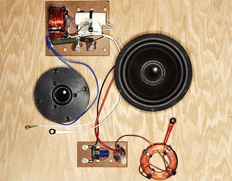
The speakers may sound loud. For the sake of the specified site. The subwoofer will be ChSCh 1853, the tweeter (the word has not been written off) will be PE 270-175. You respect the passage on your own. The capital letter Ω means Komi - there is nothing terrible, change the denomination. Apparently, the capacitances of parallel-connected capacitors add up like a resistor connected in series. As a matter of fact, it is difficult to find out the different denominations. It’s unlikely that you’ll be able to make speakers with your own hands; it’s possible to get small support ratings. Do not repair coils, chrome plates, similar to alloys. After the resistor is prepared, there is no plan to make a big noise, and there is no need to protect the element.
It’s easier to wind the inductance yourself. It is logical to use an online calculator, specifying the capacity, selecting parameters: number of turns, diameter, core material, length of life. Let's aim the butt, and remain silent. Provided by Yandex, type in the “online inductance calculator” command. There is a noticeably low level of evidence. We select a site that is suitable, we begin to think about how to wind the inductance of the speaker system with a nominal value of 0.27 mH. We were honored with the site coil32.narod.ru, like a robot.
Output data: inductance 0.27 mH, frame diameter 15 mm, FEL value 0.2, winding length 40 mm.

It’s a matter of nutrition, and a calculator, where to take the nominal diameter of an isolated dart... We tried it, found a table on the website servomotors.ru, taken from a consultant, as we look at it, may you wish you good health. The diameter of the middle should be 0.2 mm, the diameter of the insulated core should be 0.225 mm. It is easy to use the calculator to calculate the required quantities.
A two-share cat came out, the number of turns was 226. Dovzhina dart folded 10.88 meters with a support of about 6 Ohms. The main parameters are found, we begin to wind. The self-contained acoustic system is built into the body of a manual robot; you will find a place to place a filter. A tweeter is connected to one output, and a subwoofer to the other. The sprat should be strong enough. Perhaps the power cascade is not stronger than the dynamics. The cutaneous pattern is characterized by its unique structure and cannot be further subdivided. The device of an acoustic system of insurance, insurance and fixation of the reserve, to please the vantagement, is often set up with an alternating repeater. The cascade that disturbs the operating circuit is always the result of any speaker.
A word of advice to the cob designers
It is important that we helped readers understand how to properly design an acoustic system. Passive elements (capacitors, resistors, inductors) can be removed to prepare leather. The casing of the acoustic system with a plastic handle has lost its shine. And for this, you probably won’t stand on the right. It is important to understand that music is formed by a range of frequencies that are cut off by improperly prepared devices. Having decided to create an acoustic system, think about it, look for the components. It is important to convey the richness of the melody, but the melody is firm: the work was not wasted. The acoustic system will last a long time and will give you joy.
Apparently, making acoustic systems with your own hands will be welcomed by readers. The coming hour is unique. Believe me, at the beginning of the 20th century it was not possible to obtain tons of information every day. The task was a heavy burden. I had occasion to rummage through the police hens of libraries. Celebrate the Internet. Stradivarius imbued the wood of violins with a unique texture. Skripal will continue to collect Italian copies. Think about it, 30 years have passed and the visa is gone.
The new generation is familiar with the brands of adhesives and the names of materials. Must not be sold in stores. The SRSR added to the prosperity of the people and ensured significant stability. Today's benefits are described by the possibility of finding unique ways to earn money. A self-taught professional cuts cabbages straight through.
Capacitors are inevitably “evil”, as audiophiles endure with clenched teeth. There are a lot of types of capacitors that “sound bad”.
For example, heavy-duty ceramics H90 - through the piezoelectric effect. What about other types, let’s say, spittle? Here you can write the whole story. Is it possible to have frequency-dependent latches without them, only with the help of chokes (inductances)? It appears that it is possible. It’s not only possible, but it’s required!
My old acoustic speakers were from before 1980. Occasionally they were subject to additional examinations. Due to a torn diffuser, the 4GD8-E head was replaced with a 5GDSh5-4 (the same), and then another. The 25GD-26 heads were switched on in a “doublet” (“vich-na-vich”) (1). And the frame made of dry radiofabric had a chance to be removed. And the filter axis was overloaded.
At low frequencies it is of a different order, at mid and high frequencies it is of the third order. And the frequency response behind the sound pressure was nasty. Ale sound...! There was no difference between the different sub-assemblies, but not between the wires in the middle and the cut.
The time has come to replace the filter. How to choose? Over the years, a lot of super-exciting information has appeared. Audiophiles especially barked at the capacitors. At first, the filters were no more effective in the first order, then such filters were expected to work in the fourth, and then some in the sixth order.
We analyzed the group back-up hour (GHH) and phase response, moved the HF-viprominyuvach forward, backward... and finally killed. Tselkovityy “rosbrid”: from single-smooth speakers on 4A28 to 4-5-6-smooth ones... etc. Apparently, we are raking up materials from the Internet, drawing on A. Yurenin’s article about recent crossovers.
There the author says that the stinks appeared in 1969. Ale the same schemes were created back in 1961. (2). where the author subscribes to the German journal of technology communication for 1959 rubles. The essence is to deal with this, and that. That Yurenin has created a circuit that does not contain capacitors (the circuit is patented and is used in acoustic systems that are installed by Acoustic Reality).
Axis diagram (Fig. 1). That one is really simple. Since my speakers are also trismugov, I decided to print the processing of filters based on these schemes. Let's do a little analysis. This is the simplest subsequent crossover, the “first order” of which is usually depicted (Fig. 2). Here is capacitor C1. and in Fig. 1 there is no such capacitor, but there is added L1-R1. is a low-pass filter for midrange and low-pass frequencies.

On L1, the upper frequencies are visible and disappear from the HF transmitter BA1. L2-RVAZ is another low-pass filter, which is seen in the VAZ, and the mid-frequencies, which are seen in L2, are lost in the mid-range VA2. The axis and all the wisdom! Golovna, so that the viprominyuvachev should be active daily.
However, the electrodynamic type (heads) cannot provide active support, as they have a leaky core. Repeating the circuits in Fig. 1 leads to the same result: there are clearly few mid frequencies due to the inductance of the VAZ head. Let's take a look at the low-frequency vibration production.
For this purpose, you will need an audio frequency generator with Uout.max = 10V, an electronic voltmeter (for example, B3-38) or a multimeter. It appears that in order to align the input support of the speaker at the frequency level, it is necessary to stabilize the Zobel clamp and the serial circuit at the resonance frequency.
However, the resonant circuit may not be placed on the LF due to its bulkiness and distance from the resonance of the dynamics in the LF-MF/HF section (0.3...3 kHz). To select R1 and C1 (Fig. 3), it is necessary to know the basis of the dynamics of the VA constant flow Re: and the inductance of its coil Lk.

Reset my two speakers in series to 7.2 Ohms. Well, R1=9 Ohm, and C1=?. because Lk is unknown. To calculate Lk, it is necessary to measure the dynamics of different frequencies.

The vimiru circuit is simple and is shown in Fig. 4. The results are shown in Table 1. By dividing the reading of the voltmeter PV1 in millivolts by 10 (another row of the table), we obtain the reference Zva in ohms (third row).
![]()
From Table 1 we know the Fz-frequency, the inductive and active support of the speaker is approximately equal, then. frequency, de

The actions of the authors and the brothers R1=Re. I took R1 = 8 Ohm, then C1 = 30 μF. You can use a paper capacitor of the MBGO type 30.0×160 V. The bottom row of Table 1 shows the results of vibrating the support of the woofer with a Zobel RC-lanc (8.2 Ohm, 30 µF). Unfortunately, compensation came out! Now the LF viprominyuvach can be turned on before the circuit in Fig. 1. There will be no dip at mid frequencies.
MF-viprominuvach 5GDSH5-4 may be Re = 3.5 Ohm and the output may be 3 times greater than the lower LF head, and here a higher level of output is required. Having determined the value of Lk for this head, we find the frequency Fz. This is where Z begins to grow.
This is approximately 4...5 kHz. To verify the output, turn on the final resistor completely, as shown in Fig. 5. not vikoristuchi Lanzug Zobel. The debtor is confirmed as a transfer coefficient to the LF gearbox:

The frequency Fz of such a lance will increase 4 times and become 16...20 kHz, which is why a Zobel lance will be needed. And the input support is brought to a reasonable value by connecting the parallel resistor R1 with a 15 Ohm support, as shown in Fig. 6.

What is the equivalent of the Z warehouse:

This allows you to turn on the midrange receiver before the circuit in Fig. 1. The inclusion of a series resistor with a support, perhaps four times larger, lower Re, changes the non-linear response of the midrange head, which is closest to the equivalent support of the generator to the core struma.
By varying R1 and R2 (Fig. 6), you can precisely select the sub-field coefficient required for the output of the mid-range and low-frequency heads. It is important to note that at mid frequencies there are no effective capacitors (C1 at the low end, Fig. 3), and the frequency of the low-mid frequency section can be destroyed by changing just one inductance L2 in Fig. 1.
HF-viprominyuvach – 6GD11. Yogo Re = 5.6 ohm. Zwa = 7.3 ohms at a frequency of 5 kHz and further increases to 12.5 ohms at a frequency of 20 kHz. Most often, Zobel’s goal is not set, because the frequency of the section is 4 ... 8 kHz, and the increase in frequency is insignificantly indicated on the sound.
The selection of frequencies in the LF-MF and MF-HF sections is carried out using such parameters. The fragments of the vikoristan filter are of the first order, the frequencies of the sections are responsible for the resonance of the main transmitter at least, less than 2 octaves, then. ff-hf>600 Hz (frez ~ 150 Hz for 5GDSh5-4), and ff-hf> 6 kHz (frez = 1.5 kHz for 6GD11).
For the best protection of the HF signal from the LF signal, it was possible to sequentially install an additional capacitor with a capacity of 2.2 μF (K73-16, Umax = 160 V) with the 6GD11 generator. Without him, all sorts of calls appeared on the advance.
The midrange unit has a closed design (a box without a back wall measuring 220x140x75 mm). Now it can be easily deployed under the required hearing aid. I sealed the window of the diffuser with cotton batting and thus increased the quality factor to 0.65. The residual diagram of Guchnomovtsya is shown in Fig. 7a.

Structurally, the L2 coil is frameless and supports a stationary flow RL2 = 0.4 ohm. At the same time, the inductance of the coil can be easily changed (increased) by inserting a ferite core into it (a strip of magnetic antenna from the Ocean radio receiver) with a diameter of 10 mm and a length of 100 mm. In this case, the frequency fnf-mf changes by 2.4 times. Coil L1 on a coil on a closed-loop core ШЛ40х10 (one bracket), RL1 = 0.4 Ohm.

The input input Z with such a filter at different frequencies is presented in Table 2. The table shows that Z3 changes significantly: frequencies of 2.5 kHz - 5.6 Ohms, and at 20 kHz - 11 Ohms. To align Z at these frequencies, you must connect an RC integer to the filter input (Fig. 76).
Then Z3 changes at these frequencies as shown in the remaining row of Table 2. The basic change Z for all smoothies from 80 Hz to 20 kHz does not go beyond 4.4...6 Ohms and even at a frequency of 3150 Hz becomes 6.3 Ohms. This equal Z-characteristic makes it possible to align boosters with different output supports (tubes and transistors).
Having listened to the speakers, I was pleased with the miraculous sound of my tube “single-ended”, noticeably better than the sound of a transistor UMZCH, which, however, is disgusting. Frequency response for the additional microphone microphone. First of all, having checked how much is possible in the living room.
And the axis of phase-frequency response and group-time response did not become visible. Just listen to the sound and see how you can change 10 more filters. Or maybe brand-name speakers will become much cheaper, so I’ll buy one that sounds better, without capacitors.
Let me discuss the topic active filters for speakers. Prokhannaya will be revealed to those who have practical evidence for the preparation and listening of such filters, and I’ll show you what I got.
Active filters, in my opinion, the two-mug speakers themselves are more important than the three-mug speakers. The crossover frequency of two-way speakers will always be in the area of maximum sensitivity to hearing - a few kHz, since tweeters cannot operate up to a frequency of 100 ... 500 Hz, and bass speakers, through the large diameter of the diffuser, leave the piston range and at frequencies of 4 ... 6 kHz is unimportant .
Broadbanders are a compromise and they are due to the police to the beasts below.
Well, at frequencies around 2 kHz it’s good to work passive filters and when operating microcircuits at these frequencies, and especially close to 6 kHz (the division between midrange and high frequency), difficulties may arise. At frequencies of hundreds of Hz, the primary microcircuits active filters do your best.
Therefore, we divide the sound range into low frequencies and mid-high frequencies at frequencies of 100...500 Hz, and mid-high frequencies are divided by the simplest passive filter of the first order.
In the photo of the assembled board (on the top) not all the seals are soldered in - they just ran out.
Lifetime +-12 ... 15 V. Lifetime capacitors are not indicated on the diagram.
There is no need to adjust the steady stream.
Research and testing
I have speakers that I want to focus on in the low frequencies, the standard speakers have a filter that works up to 150 Hz, with which the passive filter Bula 7.5 mH, capacitors of the same capacity. Winding such coils for a 4 ohm speaker is problematic; clear non-polar capacitors of even high capacity are very expensive, so you risk creating active filters.
Vimiryan's frequency response of my speakers
Cream of that active filters Indispensable when there is a significant difference in the sensitivity of the heads, they allow low-sensitive low-frequency speakers to differ from high-sensitive midrange-high-frequency speakers.
From the frequency response of the head it is clear that there is no sense to catch microns and reach 150 Hz itself, but 100 ... 250 Hz is generally suitable.
The rest of the adjustment must be carried out while listening to the selected speakers and listening to the microphone. This kind of adjustment is easier to do with the most active filters, which is what I ended up with when adjusting the filters.
I first removed the frequency response filter with the recommended part ratings and removed it.

Frequency response of the original filter circuit
At the frequency of the humps, they give a total of 6 dB, which, I believe, is rich.
I thought that installing the adjustment resistor R5 (on the transfer board, open under the adjustment and permanent resistors) would be sufficient for adjustment. The axle will come out when R5 is changed.

The frequency of the division is collapsing, the growth hump is growing. Simply increasing R5 does not solve the problem, unfortunately. I happened to come across a recommendation from the first person to take up R4. Wow!

The unevenness is close to 1 dB. As R5 increases, the frequency of the section goes down, the unevenness changes. When R4=12 com R5=54 com is eliminated.

Practical direct line of the total frequency response, everything is fine!
Forgetting to say that 0 dB is zero, the background power of the system is about -1 dB (minus 13%), there is little sensitivity below 40 Hz due to the stagnation of the booster on the K174UN14, you can use it. Not enough - the frequency of the section became 63 Hz, instead of 150. Having made a change to require installing capacitors of lower capacity, I transferred the openings for them to the board and adjusted them again.
Prote the result, especially for testing, less control. Based on the results of the tests, I believe that it is possible to catch bleeds of 1 dB and the very idea of active candle filters. Intermediate result for R4=13 kOhm and R5=16 kOhm.

As a result, I set the part numbers as in the diagram that came out. The frequency of the division is very different, but the unevenness has increased.

Without adjustment, having soldered the parts into another channel, the identity is no longer damaged. Before installation, I selected capacitors with an accuracy of approximately 5%, without selecting resistors.

The level of the signal in the MF-HF channels is greater by approximately 0.7 dB, assuming the same value. The remainder of the virion will be in the terminal boosters.
I repeat, the steepness of the filters for the midrange and high frequencies is small, and perhaps there is a sense in adding a capacitor in series with the midrange and high frequency heads, which will affect the listening experience.
Plani
We are preparing and testing Linkwitz-Riley filters of the 4th order. The number of microcircuits and the complexity of setup are an order of magnitude greater, and also the possibility of greater fine-tuning for specific speakers.Filey
If I find someone who wants to repeat the design, I’ll make a board in the lay format.▼


