Self-contained fm receiver on a microcircuit. A simple radio receiver scheme: description. Old radio receivers. Advantages of the scheme
The simplest UKKH ES priymach, available for repetition by the radioamator-pochatkіvtsyu can be chosen for the circuit of a single-transistor synchronous-phase detector. The principle diagram of such a primach is shown a little.
The signal is received by the WA 1 antenna, the role of which can be played against the mounting rod. This signal is located at the kolyvalny circuit L1C2, using the capacitor C2 circuit, it is possible to switch between the UHF SN in the range of 65.8-73 MHz. Seen by the circuit, the voltage signal goes through the capacitor C3 with the adjustment of the transistor VT1. The entire transistor cascade is violating one hour a few functions: the functions of a phase detector, a low-pass filter, a power switch fast strumu that podsilyuvacha low frequency. Phase detection is detected on p-n transitions transistor equivalent to diode transitions. The choice of receivers can be done by extensive installation, or it can be expanded paid fee based on principle diagram, and the details in the new order are sorted out in that order, like a scheme. Coil L1 does not need a frame, for winding a drill shank with a diameter of 7 mm is taken and the coil is wound on it with a PEV 0.4 ... 0.5 mm. Coil L1 revenge 14 turns. After winding, the drill is pulled out of the coil (it can only serve as a mandrel for winding).
Transistor P416B can be replaced by GT308A, KT603B. The phone is a high-resistance small-sized one. Capacitor C2 type PDA - ceramic, for 8...30p, 5...20p or 4...15p, with a screw wrap, ruffled in the middle. As a dzherelo of life, you can vicorate the element of life of Krona at 9 V. Vimikach, for example, a toggle switch.
Nalashtuvannya shodo is simple. It is necessary to connect a telephone, a living thing and an antenna - a piece of assembly rod, which is better for them. Antenna should be hung at the window or hung on the window frame. Now it is necessary to dress the head telephones (they may have a weak spike) and wrap the rotor of the capacitor C2 to try to sound one station. If you don’t want to go out, it’s necessary to stretch the coils of the coil and repeat.
Good results cannot be achieved with such a simple receiver, but you can receive two or three stations in the VHF emergency band. Experiment with stretching and tightening the coils of the L1 coil, dozhina and rotting the antenna, and elastic life. You can replace the headphones with a resistor for 1 ... 3 kΩ and from the connection point of the resistor and the emitter of the transistor to apply low-frequency voltage to the ULF, then you can hear the speakers.
List of radio elements
| Appointment | Type | Denomination | Kіlkіst | Note | Shop | My notepad |
|---|---|---|---|---|---|---|
| VT1 | bipolar transistor | P416B | 1 | Do notepad | ||
| Z 1 | Capacitor | 12 pF | 1 | Do notepad | ||
| C2 | Replaceable capacitor | 8-30pF | 1 | Do notepad | ||
| C3 | Capacitor | 36 pF | 1 | Do notepad | ||
| R1 | Resistor | 330 room | 1 | 0.5W | Do notepad | |
| WA1 | antenna | 1 | Do notepad | |||
| IN 1 | Head phone | 1 |
For a long time, the radio receivers watched the list of the most important wineries of mankind. The first such attachments were reconstructed and changed at the same time, however, little has changed in the scheme of their folding - the same antenna, the same grounding and humming circuit for receiving an obscene signal. Without a doubt, the schemes have become more complicated with the hours of the creator of radio - Popov. His successors have developed transistors and microcircuits for the creation of a larger and more energy-efficient signal.
Why is it better to start from simple schemes?
As you understand it is simple, you can be convinced that the greater part of the path to success in the field of storage and exploitation has already been achieved. In this article, we will analyze a number of schemes of such devices, the history of their vindication and the main characteristics: frequency, range, etc.
Historical proof
January 7, 1895 is celebrated as the birthday of a radio receiver. On the second day of the Russian exercises, A. S. Popov demonstrated his equipment at the meetings of the Russian Physical and Chemical Association.
In 1899, the first line of radio communication was initiated, 45 km long, between the town and town of Kotka. Under the hour of the First Light War there were widened priymach of direct power and electronic lamps. Under the hour of the military days, the presence of the radio turned out to be strategically necessary.
In 1918, one hour in France, Germany, and the United States, L. Levvy, L. Schottky, and E. Armstrong expanded the method of superheterodyne reception, but through weak electron lamps, the principle was widely expanded only in the 1930s.
Transistor extensions appeared and developed in the 50s and 60s. The first radio receiver, which is widely victorious, on some Regency TR-1 transistors was created by the German physicist Herbert Mathare for the support of Jacob Michael's prophecy. Vіn naіyshov in sales from the USA in 1954 roci. All old radio receivers worked on transistors.
In the 70s, the development and promotion of integrated microcircuits began. At the same time, the adopters are developing for the help of great integration of nodes and digital processing of signals.
Appliance characteristics
Like old radio receivers, so modern may have singing characteristics:
- Sensitivity - ability to receive weak signals.
- Dynamic range - vibrated in Hertz.
- Perishkodostіykіst.
- Selectivity (vibrancy) - the ability to suppress third-party signals.
- Riven your noises.
- Stability.
These characteristics do not change in new generations of primaries and signify their practicality and reliability of operation.
The principle of robotic radio receivers
At the infamous looking radio receivers of the SRSR, they practiced for such a scheme:
- Through the induction of the electromagnetic field in the antenna, an alternating strum appears.
- The number is filtered (selectivity) in the presence of information in the transition code, i.e., from the signal one can see an important warehouse.
- The canceled signal is converted to sound (at the time of the radio).
Following a similar principle, images on television are established, digital data is transmitted, and radio equipment is used (children's helicopters, cars).

The first primach was more like a glass tube with two electrodes and a thyrsa in the middle. The robot was based on the principle of pouring charges on metal powder. Primach majestic majestic behind the modern worlds of opir (up to 1000 Ohm) through those that the thyrsa badly contacted with each other, and part of the charge slipped into the open space, derose. Yearly, the thyrsa was replaced by a kolyalny circuit and transistors for saving and transferring energy.
Depending on the individual scheme, receiving the signal from the new one, you can pass additional filtering by frequency amplitude, amplification, digitization for further software processing. Simple scheme the radio receiver transmits one by one the signal.
Terminology
A coil and a capacitor, closed at the lances, are called the kolyvalny circuit in the simplest of eyes. For the help of them, you can see the necessary balance of your frequency to the circuit using the signals you need. Radio receivers of the SRSR, as well as modern attachments, founded on this segment. How does everything function?
As a rule, the life of radio receivers depends on the number of batteries, the number of which varies from 1 to 9. For transistor devices, batteries 7D-0.1 and type "Krona" with a voltage of up to 9 V are widely used.
According to the frequency of signals, I will add to the following types:
- Dovgokhvilyovі (DV) - from 150 to 450 kHz (easily spread in the ionosphere). The meaning of mundane whils, the intensity of such changes on the vіdstanі.
- Mid-range (SV) - from 500 to 1500 kHz (easily rise in the ionosphere during the day, but at night they rise). At a bright hour, the radius of the day is marked by mundane whimpering, at night - it is beaten.
- Korotkohvilyovі (HF) - from 3 to 30 MHz (they do not land, they are exclusively vibrated by the ionosphere, which is why the radio zone is used for this purpose). With a small strain, the transmission of short winds can be widened by large ones.
- Ultrashort-wavelength (UKKH) - from 30 to 300 MHz (mayut temporally adjoining buildings, as a rule, they are absorbed by the ionosphere and easily go around crossings).
- - Vіd 300 MHz to 3 GHz style tie and Wi-Fi, located at the boundaries of visibility, do not bend around the crossroads and expand in a straight line).
- On the edge of high frequency (EHF) - from 3 to 30 GHz (they are used for satellite communication, they are used for switching and to be at the line-of-sight boundaries).
- Hyper-high-frequency (HHF) - from 30 GHz to 300 GHz (do not bend over the code and move like it is light, vicorist is bordered).
With varying HF, SW and LW radio communications can be carried out, moving far from the station. The UKH band receives signals more specifically, although the station only listens to light, hearing at lower frequencies is not possible. At the receiver, you can use a player to listen to music, a projector for displaying on a remote surface, an anniversary and an alarm clock. The description of the radio receiver scheme with such additions can be complicated.
Implementation in the radio receiver of the microcircuit made it possible to significantly increase the radius of the reception and the frequency of the signals. It’s a big trouble for a relatively small energy saving and a small expansion, which is handy for transferring. The microcircuit will remove the necessary parameters for signal downsampling and readability of the output data. Digital processing of the signal dominates in modern outbuildings. were recognized as less than the transmission of the audio signal, less than the remaining ten years of receptions rose and fell.
Schemes of the simplest methods
The scheme of the simplest radio receiver for picking up a booth was broken up in just one hour of the SRSR. So, like at once, they were divided into detector, direct settlement, direct conversion, superheterodyne type, reflex, regenerative and supraregenerative. The most simple among the spriynyatti that folded in vvazhayutsya detector priymachi, s of which, you can vvazhat, having started the development of radio on the cob of the 20th century. The most collapsible have steel attachments on microcircuits and several transistors. However, even if you get it right in one scheme, it won't be a problem otherwise.
Simple detector primer
The scheme of the simplest radio receiver contains two details: a germanium diode (due to D8 and D9) and head phone with a high support (TON1 chi TON2). So, as there is no ringing circuit in Lancia, you can’t catch the signals of a singing radio station that are broadcast in Denmark, you can’t, but you can’t get into your main tasks.

For a robot, you need a good antenna, you can throw it on a tree, that wire is grounded. For fidelity of yoga, it is enough to come to a massive metal trap (for example, a bucket) and bury a sprat of centimeters near the ground.
Variant with a kolyalny contour
At the end of the circuit for vibrating stasis, you can add an inductance coil and a capacitor by creating a kolyvalny circuit. Now for the bazhannya it is possible to vilify the signal of a specific radio station and to navit force yoga.
Lamp regenerative short primach
Lamp radio receivers, the scheme of which to communicate is simple, they are prepared for receiving signals from amateur stations. small stands- in the range of UKKh (ultra-short-quilled) to DV (double-quilled). Finger batteries are used on this scheme. The stench is the best to generate on the UKH. And the opir of the anode bias takes a low frequency. All the details are shown on the diagram, self-confidently you can take in more than a cat and a throttle. What do you want to accept TV signals, then the coil L2 (EBF11) is made up of 7 turns with a diameter of 15 mm and a 1.5 mm wire. For pidide 5 turns.
Radio receiver of direct power on two transistors
Scheme of revenge and two-stage substation of the LF - the main input of the radio receiver circuit, which is to be tuned. The first stage is the RF modulated signal detector. The coil of inductance is wound in 80 turns with a wire PEV-0.25 (see the sixth turn at the bottom of the diagram) on a ferite shear with a diameter of 10 mm and a winding 40.

A similar simple scheme of a radio receiver is covered for the recognition of strained signals from nearby stations.
Supragenerative attachment on the FM band
FM-receiver, selected for the model of E. Solodovnikov, clumsy in folding, but may have a high sensitivity (up to 1 μV). Such attachments are for high-frequency signals (greater than 1 MHz) with amplitude modulation. Zavdyaki strong positive zvorotny zv'azku the coefficient grows to inconsistency, and the circuit is converted to the generation mode. For reasons of self-excitement. In order to unify and victorize the receiver as a high-frequency subsiluvach, set the ratio of the coefficient i, if it reaches the value, sharply change to the minimum. For permanent monitoring of the power, you can use a generator of saw-like impulses, or you can build a simple one.

In fact, quite often the pidsiluvach himself acts as a generator. For additional filters (R6C7), which signals are seen low frequencies, between the passage of ultrasonic coving on the input of the ULF offensive cascade. For FM signals of 100-108 MHz, the L1 coil is converted into a loop with a 30 mm crossbar and a linear part of 20 mm with a diameter of 1 mm. And the coil L2 should be 2-3 turns with a diameter of 15 mm and wired with a 0.7 mm pereline in the middle of the winding. Possibility of receiving stronger signals at 87.5 MHz.
Attachment on microcircuits
HF radio receiver, the scheme of which bula was broken up in 70 years, immediately enter the Internet as a prototype. Short-range signals (3-30 MHz) will rise in price on long distances. It doesn't matter if you set up a receiver to listen to the broadcast in another country. Behind this prototype, otrimav the name of the light radio.

Simple HF receiver
The simple scheme of the radio receiver has been added to the microcircuit. Overrides the range from 4 to 13 MHz for a frequency of up to 75 meters for a long time. Zhivlennya - 9 V in the type of battery "Krona". As an antenna, you can have a mounting wire. Priymach works on headphones from the player. High-frequency treatise of impulses on transistors VT1 and VT2. For the rahunok of the capacitor C3, a positive charge wraps, regulated by the resistor R5.
Modern radio receivers
Modern devices are even more similar to the radio receivers of the SRSR: the stench of the same antenna is blamed for the weak electromagnetism. In the antenna, there are high-frequency sounds of various radio stations. The stench vikoristovuyutsya without intermediary transmission of the signal, but zdіysnyuyut the robot of the advancing lancet. Such an effect can be easily reached with the help of heating equipment.

A wide development of the priymachi was taken off in the middle of the 20th century and from quiet fir they were constantly adorned, regardless of their change mobile phones, tablets and TVs.
Zagalny pristry radio receivers from Popov's watch changed with an insignificant rank. It can be said that the circuits have become much more complicated, microcircuits and transistors have reached, it has become possible to receive not only an audio signal, but also a projector. So the adopters evolved at the TV. At once, for a bazhannya, you can bring into the apartment everything that your soul zabazhaє.
What is an FM receiver? Radio receiver - ce electronic attachment, as if receiving radio waves and transforming information, as if to endure stench, into a box for a human being to take. Receiver of the vicorist electronic filter, to remove the required radio frequency signal from the other signals that are captured by the antenna, electronic booster to reduce the intensity of the signal for further processing, and demodulation.
Z radiohvil, FM is the most popular. Frequency modulation is widely used for FM radio broadcasting. The advantage of frequency modulation is affected by the fact that there can be more signal / noise ratio and, therefore, the radio frequency transitions are less pronounced than the signal of amplitude modulation equal tension (AM). The sound from the radio receiver is much cleaner and richer.
FM frequency bands
UKKh (UltraShort-Khvilyovy) range z ChS (Frequency Modulation) for the English FM (Frequency Modulation) may be up to 10 m to 0.1 mm - ce to frequencies from 30 MHz to 3000 GHz.
For the reception of the current radio stations, a relatively small lot is relevant:
UKKh 64 - 75 MHz. This is our radian range. There are a lot of UKH stations at the new one, and even less near our country.
Japanese band from 76 to 90 MHz. At this range, the movement is carried out in Japan.
FM - 88 - 108MHz. - This is a good option. Most of the primaries, which none of them are for sale, generally work in the same range. Often, at the same time, they accept our soviet range and zahіdny.
UKKh radio transmitter may have a wide channel - 200 kHz. The maximum audio frequency that is transmitted in FM is 15 kHz versus 4.5 kHz in AM. Tse allows you to transmit a wide range of frequencies. In this order, the quality of FM transmission is significantly higher, lower AM.
Now about the receiver. Below is a diagram of the electronics for the FM receiver along with a description of the robot.
List of components
- Chip: LM386
- Transistors: T1 BF494, T2 BF495
- Coil L to sweep 4 turns, Ф=0.7mm on a mandrel 4 mm.
- Capacitors: C1 220nF
- C2 2.2 nf
- C 100 nf x 2 pcs
- C4.5 10uF (25V)
- C7 47 nF
- C8 220uF (25V)
- C9 100 microfarad (25 V) x 2 pcs
- Opir:
- R 10 pcs x 2 pcs
- R3 1 com
- R4 10 Ohm
- Zminny opir 22kOhm
- Change capacity 22pf
- Speaker 8 ohm
- Vimikach
- antenna
- Battery 6-9V
FM receiver circuit description
Below is a diagram of a simple FM receiver. Minimum components for a receiving FM station.
Transistors (T1,2), together with a 10k resistor (R1), a coil L, a replacement capacitor (VC) 22pF add up an RF generator (Colpitts oscillator).
The resonant frequency of this oscillator is set by the VC trimmer to the frequency of the station you are transmitting, as you wish to receive. Tobto, vin is guilty of buti nalashtovaniya mizh 88 and 108 MHz FM band.
The informational signal, which is taken from the T2 collector, goes to the LF subwoofer on the LM386 through a separate capacitor (C1) 220nF and a 22 kOhm VR loudness regulator.
FM receiver important wiring diagram

Basic electrical diagramFM primach
Perebudov's station is equipped with a changeable capacity of a changeable capacitor of 22 pF. If you want to win, if there is any other capacitor, which may have a large capacity, try changing the number of turns of the coil L to adjust to the FM band (88-108 MHz).
Coil L maє chotiri coils of enameled copper dart, 0.7 mm in diameter. The coil is wound on a mandrel with a diameter of 4 mm. Її can be wound on any cylindrical object (sheep or handle with a diameter of 4 mm).
If you want to receive a signal from the UHF stations (64-75 MHz), you need to wind 6 turns of the coil or increase the capacity of the replaceable capacitor.
- 08.10.2014
2N3819 Analogue of OU 741 K140UD7, 2N3819 Analogue of KP307B Dany switch ensures a constant level of the output signal with a significant change of the input signal. OU vikoristovuєtsya as podsiluvach stіyny strumu, poslennya koto lie down in іd spіvіdnoshennia R2/R1 і dilnik voltage on R4 і support field effect transistor. The transistor plays the role of a resistor in this circuit, yogo opir.
- 20.09.2014
Classification of magnetic materials Magnetic materials are widely known in electrical engineering, without them, at this time, electrical machines, transformers, electrical equipment are inconceivable. Fallow in the presence of stosuvannya to magnetic materials are presented differently, and sometimes along the way. Magnetic materials are classified into large groups after the sign of freezing: soft magnetic hard magnetic Let's take a look at their characteristics briefly. …
- 20.09.2019
The alarm clock is made up of the Arduino Nano (Uno) board, the LCD indicator 1602 with the I2C module based on the PCF8574 microcircuit and the real clock module DS3231 (ZS-042). On the LCD 1602 indicator, the big digits show the year and the length, the big digits of the second. There is only one alarm clock at the time, and it allows you to set an hour for spratsovuvannya for hvilini.
- 05.10.2014
Dynamic range - 25 ... 150 Hz, the author zastosovan low-frequency head 75GDN-3. Housing Small. 1.2. made from chipboard with a thickness of 20mm. The walls of the body are connected one by one with slats 20 * 20mm for additional glue and screws. Acoustic panel with vents for woofer The head is fixed in the middle of the speaker cabinet. The back wall of the body is installed, woofers are installed on it.
Workshop for pochatkіvtsіv.
View of the detector primach to the superheterodyne.
Self-made radio constructor. part 6
So it turned out that the 3rd part of the radio amateur designer, assigned to the UKH priymachi, rushed forward, shards of facultative occupations. Therefore, I will clean up this glade and in this settlement, we will tell you about the simplest detectors and direct reinforcement of the UHF (FM) range.
In Moscow, radio stations operate on two bands. In two bands, frequency modulation (FM) is vibrated, and in all cases of foreign vibration, this type of modulation is briefly indicated by FM (frequency modulation - frequency modulation). At the translation, the letters FM are chanted and the same.
Since the 1990s, imported radio receivers with the UKH 2 (FM) band have flooded the market, and in present moment ether is being mastered by radio companies, and there are already more than 40 stations in this region.
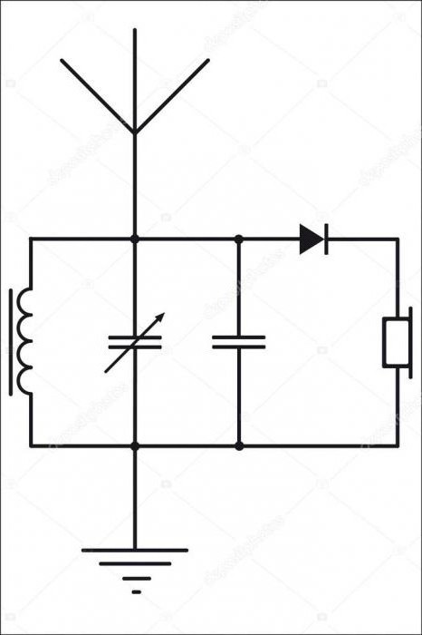
| Rice. 1. Detector UKKh (FM) priymach. |
The simplicity of the design of the detector UKKh is calming. Z'ednuye at once three - four parts, and a few radio stations in earphones. In the minds of the minds, de richly reshkod tsey priymach pracyuvatime is shorter, lower vikonations on the middle or long winds, it’s true, mind you, what a radioman UKH transmitter or the repeater is located near your booth. At my point of view, the range of the received receiver became six kilometers.
Who needs such a primach? Detector, the simplest, destruction behind the classic scheme? Sob povisti on qi nutrition, choose this design, and if you choose, then you will understand that you spent an hour not without reason. A lot of cіkavih doslidіv can be carried out with a simple priymach. Perhaps you want to improve yoga, add a power cascade, improve selectivity, build an antenna with a great power factor, etc. Those who don’t stop at what they have achieved are already good.
Detector UKKh priymach.
Tse Bulo is similar to an old frigate. Iogo case, volumetric resonator, length 0.75 meters (4th part of the length of the length = 3 meters, which is 100 MHz) through the blocks on the das of the zamіskogo booth. I’ll watch this episode before the midsummer heat, but in the place where the metal is going to work, I’ll just get a germanium diode to it with high-ohm headphones.
 |
| Rice. 2 Detector UKKh (FM) receiver with ULF, 0 - V - 1. |
The simplest UHF FM detector receiver behind the circuit is not connected to the amplitude detector of the ranges: DV, SV, HF, but for the design of the wines it can be used with an inductance coil, there is only a little bit of a winding. Such a circuit with a capacitor of variable capacity of about 30 pF overlaps twice 2 bands with a margin of 65 to 108 MHz.
With the method of increasing the quality factor, vrahovyuchi, HF jets flow over the surface of the wires, I selected a diameter of 2 mm, a vicorous honeydew for electrical wiring, having removed the new insulation and wound 4 turns on a mandrel with a diameter of 1.2 cm.
 |
| Photo 1. Inductance coil. |
Detection of an emergency signal in sound frequency comes in two stages. The emergency signal will turn back to AM, because the call to the radio station will sound on the scale frequency response to the circuit, which should lead to a change in the amplitude of the emergency signal (the higher the frequency, or the greater the amplitude of the overflow, the more the amplitude of the signal and the changes will change). Transformation, AM signal is converted to the sound frequency by the amplitude detector on the diode.
But if you feel the air from such a receiver, it is possible to transmit in an uninterrupted proximity, so you can connect the VLF with a low-resistance telephone or a computer speaker, so as a slope to the circuit at the frequency that is received, even a gentle change in the amplitude of the frequency signal in the result of the conversion small. If I came all the way, then I myself was crying, what can I smell. The edge of the ringing circuit may be at this frequency close to 5 MHz, which means that close to 10 stations I may almost at once.
In practice, I first chose such a simple radio receiver for a frequency for an emergency signal.
Detector priymach, vikonanie for the voltage boost circuit (for Villiard) Fig. 3, in practice, it will not give a big difference in accuracy (by 2 times or by 6 dB). With such an included diode, the circuit will be stronger than the attraction, and in order to improve the quality factor, it will be necessary to change the turn-on coefficient, or an omniscient sound, and in a shorter fall, the sound will be 4 dB better, it’s not audible. The deputy of german diodes, who have long been out of production, have badly recommended low-frequency PIN diodes for this scheme. I have long been vicorist, for the characteristics of the stench are closer to german diodes. Div. "Forgive the low-frequency field indicators with your own hands."
The toy turned out to be gummed. I was far away to get up to five radio stations. Obviously, the stench was respected one by one, the music of one was superimposed on the language of another station, but in general, having received the air, it was possible to know the village in the range, if the hard radio station, ignoring the distance, sounded comfortable. And with the best antenna in the minds of the people, a daily rule was revealed, such an aluminum bar for vibrating the walls. Її dozhina 1.5 meters, lower linear non-slit vibrator for the range of UKH 2. The detector was not required for the grounded UKH, and it was better to win in pairs with AM, we will take it, just to compare it for the same number of details.
Ale, while having left one hundred nedolіk, selectivity is bad, or vibrkovіst along the main canal, well, just a communal, like a toy in retro style, the memory of childishness, about the huge kitchen will be reminiscent of the succes with their tiles and roses. And from the other side, you can hear the music, and at the same time you know about the new weather from the other radio station.
I tried the polypshit quality of the circuit, to increase strength and achieve good vibrancy along the vascular channel, for which I built a coil with an aluminum tube, fixed it in a “basin for cooking”, and constructed a similar resonator. I didn’t care about those who received the radio stations, I didn’t win real.
 |
There was another idea to attach a straight-lined spiral antenna to the basin with a high coefficient of strength, a vicorous water pipe with a coil diameter of 0.5 meters and a length of crochet winding up to 5 meters, but during the period of alcohol consumption, the result of a drop in alcohol consumption yut on new, such a design would make a moonshine of a virobnic scale. From the vіdіvka I had a chance to look.
Zastosuvannya.A lot of dozens of such devices, which are formed from vibrators at the sight of wires, directing to the nearest transmitter, fumigation contours, tuned to a hard radio station, and the same number of diodes, and - ready to use less energy, like a loan of less money, lower similar detectors-accumulating LW and MW bands.
I tried to get rid of nasty susіdіv and put another resonant cascade stronger in front of the detector, which will change, robbiv, in such a rank,
priymach UKH (FM ) direct amplification 1 –V - 1.
When violating 2 resonant circuits, the smuga is guilty of sounding 1.4 times, and the strangulation of the suture channel is increased by 2 times, which happened in practice, but to make a wide smuga (3.5 MHz), which was lost, spluttered at two stations. Such a design worked only in the city, but in the countryside city, 70 km from the city and 20 km from the repeater, I did not manage to slander the railway station, only the equal white noise of the ULF. It’s true, I’ll have to go to the television antenna with a subdued, now it’s starting to show up on equal noises, but I’ll build it farther away for a better functioning. For normal work such a reception, it was necessary for me to turn around in the 50s of the last century and to change the scheme of the KVN-49 television, the primary path of which I will add was broken up behind the scheme of direct reinforcement. Primach mav is less than two channels. This was a line of lamps with contours, as if they were mumbling with a vazhel-permikachem, which locks the contact pads along the entire length of the road. And more than 20 years ago, if the FM band has not yet been mastered, such a self-confident trick turned out to be quite acceptable to the victorious, accepted, to the minds of the people. I didn’t want to turn around to the past with the method of simplifying the scheme.
Zastosuvannya. A scheme of a resonant substation was induced (Fig. 5), it was tested for an hour and it was successfully completed until the next day preselector V superheterodyne receiver. In more serious devices, all sub-construction and replacement capacitors are replaced by varicaps, and the installation at the station is carried out for the help of a microprocessor.
Non-perebudovuvanny resonant podsiluvach HF to know zastosuvannya for a distant call, being a vikorist in the capacity of an antenna podsiluvach, installations without intermediary in the antenna. Zavdyaki vuzkiy smuzі priyomu, vіn matime less noise coefficient, the ultimate zahist in the case of a shift between the pairs with a wide-range aperiodic cascade, which is more importantly victorious in standard antenna subs.
Turning to those simple tricks of the UKH of direct reinforcement, I, perhaps, will look at the growth of the contours with the method of sounding the smog of the transmission, and I will take the over-regenerative detector cascade for the range of UKH-2
Supraregenerative primach UKH (FM) band.
Not succumbing to a happy person at the moment, if she was demonstrating the work of her supra-regenerative prime. There are three transistors on cardboard, pinning an antenna and a sprat of distant stations, choking with foreign language, interrupting one another.
I also chose similar HF receivers for radio-ceramic models and simple intercoms. This type of signal detection is subdued by its simplicity, but at the same time it goes over to the retro category, acting like a superheterodyne prime, which is a kind of modern elemental basis for the mother.
Ale, you need to watch out for the building, more than having it, you can’t see the new one, twisting the substroyuvalny capacitors, picking up the modes, domaging the convenience of the circuits, etc. e. in the test, take into account the type of radio receiver that is above nature, as it is sings out of its name. I won’t rozcharovuvat anyone, that he himself chose such a receiver for the range of UKH - 2 (88 - 108 MHz) and I’ve been over him for more than one evening.
 |
| Rice. 6. UKKh (FM) priymach іz supraregenerative detector. 1 - V - 1 |
This priymach has better selectivity for the land channel, having practically moved to a nearby apartment. Better sensitivity, I can already hear yoga in the country. Ale about reshta parametrіv me more quickly help. And then all the interest is lost to the new and happy person, as if demonstrating the robot of the primach, no one should be sued for pleading.
The design of the receiver is similar to the front one, but if you don’t have to screen the super-regenerative detector, then put your hand up to the demodulator coil, you can change it, even if you turn on the high frequency generator low frequency. tse vikonano one transistor. I specially changed the forward circuit a little, having converted the UHF resonant cascade to an aperiodic one, so that such a design could easily be rebuilt. Change the detector more importantly. I'll make a better connection with the antenna to secure the UHF cascode. Everything about it is written in 3 parts of the radio amateur designer.
Such a simple UKH radio receiver can be used to look at a layout in a retro style, which can be played at a school exhibition of creativity, as a practical task for a vacation. As a demonstrative radio receiver, it will be more practical in the minds of people, de richly shifted, aligned with the NE and LW bands.
marvel planting"Lamp regenerative FM band detector".
In this post, the layout of the direct reinforcement for the scheme 0 - V - 1 was selected. active column and the receiver is ready. At the locality, the reception is carried out on a shtirov antenna without grounding. Send a ticket to the childhood of the past and choose this retro design. Don't mess around!


