TV test signal generator on Pic. Signal generator for regulation of televisions I'll build a robotic algorithm
The generator is connected to the antenna input of the TV, which works on the first or other TV channel. Looking at the different types of images on the screen, you can change the color of the kinescope, achieve purity of color and balance of white, correct the geometrical creation, reconcile the centering of the raster, adjust the focus thinly. The attachment forms a black and white field, six and twelve vertical smugs with gradations of lightness, vertical and horizontal lines that are drawn, as well as check and match of the field and many other combinations, among which the signal can be inverted. With the method of simplicity, the generator forms a row raster with the number of rows 315. The frame rate is 49.6 Hz. Schematic diagram generator shown little. Vіn is made up of a quartz oscillator of a single frequency (DD5.1, DD5.2), a TV signal former (DD1 - DD4, DD5.3, DD5.4, DD6, DD7), an add-on device (VD5 - VD7, R17 - R19) and RF generator (VT1) Quartz oscillator vibrates pulses with a forwarding frequency of 4 MHz.

As a result, on the output of the 15th VD2 lamp, on the 16th input pulse, a pulse of 0.1 μs is formed, satisfying the signals with a frequency of 250 Hz. creating vertical smog on the screen. Vіdbuvaєtsya on jumper SB5. Divide the frequency of repetition of the sequence of the qualifier D1 to a small one (15625 Hz), at the output 1 we take the signal of vertical swarms, which should go to the jumper SB4.1. Resistors R2 - R5 reshape the signals double code on the outputs 1, 2, 3, 4 of the lighter DD1, the voltage of the gradation of brightness often changes in steps. Rows extinguish and synchronize pulses with a passage period of 64 µs. are formed by triggers of the D3 microcircuit. Before the appearance of an impulse at the input R, the flip-flop DD3.1 is in a single station. Enters the input R impulse, installs it in the zero camp, which gives the cob the formation of a row impulse, which is extinguished. Trigger turns to holiday camp under the influx of yogo input 3 of another positive difference, which results in the output of 1 lichilnik DD1. On the inverse output of the flip-flop, positively extinguish the pulse trivality of 12 μs. Trigger DD3.2 forms a small sync pulse trivality of 4 µs, the front of such failures is 2 µs to extinguish the front. Take care of the elements VD1 and R6, which are used to set the ABO operation and control input D. For this trigger, frame sync pulses are inserted into the row sync signal, which should go to input R, as a result of which a sum of sync pulses is formed on this output. On microcircuits DD4, DD6 and elements DD5.3, DD5.4, it is possible to form a personnel sync pulse and signals in horizontal lines and smog. The formation of a signal of horizontal smugs occurs during the passage of impulses, which are taken from the output of the lichilnik S1 DD4, through the trigger DD6. With this, the frequency of the straightening changes twice, and the sparing becomes equal 2.

On the elements DD7.1, DD7.2, R14, VD3, there is an attachment, in which of the two outgoing signals that go to the input of the element DD7.1, the third one is formed. To remove the checker or sieve field, one hour press on the buttons SB4, SB6 (vertical and horizontal swirls). When you press the SB8 button, a dot field is removed. Various combinations of buttons SB1 - SB9 allow you to view the faceless images on the screen. The latest video signal of positive polarity is established at the add-on on the elements VD5 - VD7, R17 - R19. With one-hour pressing of the buttons SB3, SB4 and SB6, a check field signal is formed at the attachment, the square of which is filled with smogs of gradation of brightness. The video signal is taken from the resistor R19, it goes from the capacitor C3 to the RF generator, the modulation of the collector of the transistor VT1 is deactivated. The prefix to the attachment is selected in the same building on the okremіy other payment. It allows you to change the color synchronization of the robot and the entire path of the passage of color signals, adjust the frequency detectors in the color blocks. The prefix ensures the shaping of the sampled images of colored smugs that are drawn. In the mode of rechecking frequency detectors and the installation of zeros, the signals of the present colors are transmitted across the entire field through the row.

The function of the entire path of color-difference signals in the control of the image on the screen of color swarms. With this, including different testing signals of the generator itself. The principle diagram of the console is shown a little. It consists of quartz oscillators of color synchronization frequencies of 3900 kHz (elements DD4.1, DD4.2) and 4756 kHz (DD5.1, DD5.2) and color transient 4250 kHz (DD3.1, DD3.2) and 4406 kHz ( DD8.1, DD8.2), frequency switches for color synchronization (DD4.3, DD4.4, DD5.3, DD6) and color synchronous (DD3.3. DD8.3, DD10), adder (DD7, R4 - R6 , R9 – R11), clock interval generator (DD9) and pulse shaping (DD1, DD2, DD3.4, DD5.4). The prefix is activated by the QB1 button. Three small sync pulses, which are located at the prefix from the generator, the DD2.2 trigger forms pulses of the pvryadkovo frequency. І trivality (64 μs) for signal switching and color synchronization. From the output of the trigger, the stench is poured directly onto the DD5.3 element through the DD1.3 inverter to DD4.3, like in a row, I pass the signals of the color synchronization frequencies of 4756 and 3900 kHz through the row. After the summation of these signals in the DD4.4 elements, the frequency packets of color synchronization come in the DD6.1 and DD6.2 elements. In addition, from the outputs of the trigger DD2.2 and the inverter DD1.3, the pulses of the order frequency through the contacts SB2.1 and SB2.2 are switched over by the elements DD8.3 and DD3.3, as well as through the frequency signals of the frequency of the supply colors of 4406 and 4250 kHz on the element. DD10.1 and DD10.2. At the adder on the elements DD7, R4 - R6, R9 - R11, the signals of color synchronization and color synchronization are added and through the capacitor C1 they go to the point of connection of resistors R17, R18 and the diode VD7 of the generator and then to the RF autogenerator, iodulating the TV signal. Figure 5 shows a double-sided board for the selected prefix.

The signal generator is alive with a stabilized voltage, the diagram of which is shown in a small way. Svіtlodiod HL1 vіdobrazhaє vіmknennya pristroy. Details. The coil of the L1 generator is placed 8 turns on the PEV-2 0.23 wire and is wound turn to turn on a frame with a diameter of 5 and a length of 15 mm with an SCR-1 pilot core. On this frame, there is a turn of the L2 link from the same dart. Transformer T1 - be it small-sized, the expansion of the strum at the secondary winding is less than 0.3 A at the output voltage of 8 U. All the details of the signal generator in the installation of a double-sided other board. The board is shown from two sides to the little 4. The quartz resonators in the attachment can be replaced by the last coil circuits, which can be wound on a turn to a turn with a PEV-2 0.23 wire on ribbed frames with a diameter of 7 mm from the SCR-1 attachment (in the case of the Meridian radio receiver). At a frequency of 3900 kHz, for a 4 MHz receiver, for a generator, the circuit coils should be 75 turns each, the capacitance of the capacitors is 62 pF. At a frequency of 4756 kHz, the coil should be placed 60 turns, the capacity of the capacitor is 51 pF. At a frequency of 4250 kHz - 58 turns, capacitor 68 pF. At a frequency of 4406 kHz - 48 turns, capacitor 82 pF.

Setting up the signal generator. When the 4 MHz circuit is adjusted in the generator, connected to the TV, the first step is to achieve a stable row synchronization on the TV screen, and then, by pressing the SB5, SD7 buttons, the field reaches the evenness of the sides of the squares. To adjust the contours at the console, turn on the SB9 button on the generator - invert, and on the console QB1 and SB1 (blue and green smog). Wrapping up the 4756 kHz contour, they reach a stable image of the color swarms of turquoise, and then, when the 3900 kHz contour is adjusted, a bright green color. Then, press the SB1 button and adjust the contours for 4250 and 4406 kHz to remove the glow of red and white smog. If it means that the AGC is incorrectly adjusted in the TV when the signal generator is connected, the image may be created. It is necessary to adjust the AGC at the TV set. The author of the design is Valery Ivanov. Email: [email protected]
The timer forms the hourly intervals of the preset trivality, Clock 1 takes into account the number of pulses, and if necessary, changes the hourly intervals that are generated by the timer. Lіchilnik 2 vіdrakhovuє nebhіdnu іlkіst іmpulsіv і, razrahuvavі і predetermined value, zupinyaє timer.
I'll build a robotic algorithm
Timer T1 forms an hourly interval of a given trivality, after the completion of the interval in the form of a reset, to which value it is updated. In this manner, it is possible to formulate whether the sequence of impulses is from any parameters (period, trivality, spalling).
The reset subprogram starts from the reset - if there is no remaining pulse, as if it is still, the timer starts. As always, a re-test is carried out, either pulse or pause between pulses (impulse duration - 2500 μs, pause duration - 7500 μs), in this order, hourly intervals of the pulse and pause are formed according to the frequency.

Description of CTC mode
Timer skip mode pіd h zbіgu (STS)

Rice. 1. Block diagram of T0
In STS mode (WGM01, WGM00 = 0b10), the OCR0 register is checked for setting the renter's rent. Every time the CTC mode is set and the qualifier value (TCNT0) is set to the value of the OCR0 register, the qualifier is reset to zero (TCNT0=0). In this order, OCR0A sets the top of the rahunka of the litter, and, also, the second division of the building. AT this mode more wide range of regulation of the frequency of rectilinear impulses that are generated is ensured.
In the timer reset mode when starting (WGMn3-0 = 0b0100 or 0b1100), the timer intervals are set by the OCR0A register. In the CTC mode, the lichnik reset (TCNT0) is required, which means that the value of the match falls in the value of the OCR0A register. In this mode, it is possible to regulate the frequency of the rectilinear pulses that are generated. The hourly diagram of the timer operation in the STS mode is shown in small 1. The timer (TCNTn) increments its time until it hits the OCR0A value, and then the timer (TCNT0) is discarded.

Rice. 2 Timing diagrams for STS mode
Crimium dropping when you can generate a change for additional ensigns OCF0A, high-ranking registers, which are victorious for the task of the upper boundary of the rahunka. Even though a resurfacing is allowed, a resurfacing procedure can be performed to update the upper border of the chest.
To generate a signal in the CTC mode, the OC0A output can be switched to change the logical level in case of a skin tone, for which it is necessary to set the muting mode (COM0A1, COMA0 = 0b01). The OC0A value will be present on the output port, only for which output of direct output jobs. Maximum frequency generated signal is equal to fOC0 = fclk_I/O/2, thus OCRnA = 0x0000. For other values of OCRn, the frequency of the signal to be generated can be determined by the formula:

de change N determines the prescaler coefficient (1, 8, 32, 64, 128, 256 or 1024).
Program
Include"m16def.inc"
rjmp RESET; ResetHandler
reti; IRQ0 Handler
reti;;rjmp EXT_INT1 ;IRQ1 Handler
reti; reti; jmp; TIM2_COMP; Timer2 Compare Handler
reti;;reti;jmp;TIM2_OVF; Timer2 Overflow Handler
reti; ;reti;jmp;TIM1_CAPT; Timer1 Capture Handler
jmp TIM1_COMPA; Timer1CompareA Handler
reti;reti;jmp;TIM1_COMPB; Timer1 CompareB Handler
reti;reti;jmp;TIM1_OVF; Timer1 Overflow Handler
reti;;reti;jmp;TIM0_OVF; Timer0 Overflow Handler
reti;;reti;jmp;SPI_STC; SPI Transfer Complete Handler
reti;;reti;jmp;USART_RXC; USART RX Complete Handler
reti;;reti;jmp;USART_UDRE ; UDR Empty Handler
reti;reti;jmp; USART_TXC; USART TX Complete Handler
reti;reti;jmp; ADC; ADCConversion Complete Handler
reti;reti;jmp ;EE_RDY ;EEPROM Ready Handler
reti; reti; jmp; ANA_COMP; Analog Comparator Handler
reti;reti;jmp ;TWSI ;Two-wire Serial Interface Handler
reti; reti; jmp; EXT_INT2; IRQ2 Handler
reti; Timer0 CompareHandler
reti;reti;jmp SPM_RDY ;Store Program Memory Ready Handler
ldi r16,high(2500)
ldi r16, low(2500)
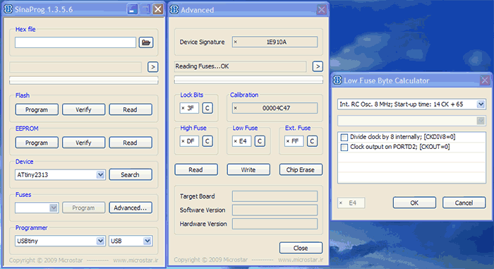
ldir16, (1< ldir16, (1< ldir16, (1< ldi r16,high(RAMEND) ldi r16, low (RAMEND) out SPL,r16 ;initialize stack sei ; enable interrupts main: ;main loop ldi r16,high(2500) ldi r16, low(2500) ldi r16,high(7500) ldi r16, low(7500) After the start of the microcontroller, the initialization procedure (RESET) is invoked, for this subprogram in sequence: Adjust port and I/O (port D is adjusted for viewing) Set up the T1 timer robot: The number (2500) is entered into the register Visnovok OC1A shifts to “reversed” equalization when changing the right register and the right register (OCR1A) The operation mode is set (skid for zbіg) and dzherelo clock signal (without prescaler, according to the system clock signal) The robot is allowed to restart for a T1 increase The stack is initialized (the top of the stack is set) Permission is granted. On which controller initialization is completed. We gave a number of "ide" commands to the main loop. In case of a failed reset, the TIM1_COMPA reset processing subprogram is started, it starts with an increase in the number of resets (a sequence of eight pulses is set, and the goal is 16 "turning the line"), the number of resets is restarted from 16, pulses, so one pulse is launched. It has a timer (zeroing the key registers of the microcontroller). Even if the number of interruptions is less than 16, the program is three years away. Re-verification of the breq pulse ensign, and, as soon as it is set, the pulse subprogram is launched, the offset register is updated (the number 7500 is taken over), and the ensign is dropped. In such a rank, for the obviousness of the ensign, the numbers 2500 and 7500 are vanquished, and on the sighting of OC1A a sequence of sparuvatistyu 4 (for orders) is formed. Probe-generator of TV signal selection on the basis of the microcontroller series pic12f629, and due to the complexity of dimensions, compaction of the stream, variability of preparation, the accessory for the telemaster is simply indispensable. The voltage of life is 3 volts, tobto. two finger batteries. Strum consumption in generation mode is 11 mA, in sleep mode - a total of 3 mA. To generate a video signal, just one microcontroller and two resistors are sufficient. So you can literally create a small video signal generator from the key fob. Such an attachment will become a good thing for a telemaster. Yogo can be victorious with the kinescope, adjusting the purity of color and linearity. The generator robot has the same characteristics. The switching between the fields is caused by short-hour (trivality less than 1s) pressing of the S2 button. Press the button in the pressed station for three hours (up to 1 s.) until the generator is turned off (the microcontroller goes to the "SLEEP" station). The generator is boosted by pressing the S1 button. About the camp of the attachment (in / out) signalizes the light. Technical characteristics of accessories: Scheme. For shaping the video signal, the zero bit of PORTA and the entire PORTB are overridden. (This port works in the suvu mode. Irrespective of those that the signal is received only from the 1st zero bit, the program will beat the whole thing. Therefore, all the PORTB bits are set as expected.) The first bit of PORTA is beaten to indicate the generator. If the attachment is fixed, the light will burn. If the attachment is broken, - the light of repayment. The third bit of PORTA is played for switching modes in the robotic generator and switching it off. A short press of the S2 button will allow me to switch from one field of the generator to another. When pressed, the button at the pressed station is longer than 1 s. prilad wimikaetsya (microcontroller go to the mill "SLEEP"). In order to increase the generator, it is necessary to remove the data. The purpose is to push the button S1. The voltage of life of the attachment can be selected between 3 - 5 V. With which fault, but the values of the resistors are selected. Program. Rozgin PIC16F84. Ready. I work with electronics, I want my mother to have a signal generator in various forms. Recently, I needed to take a sinusoidal signal for the help of digital methods, and I saw that I will get my own good generator! As a result, I have created a simple, but functional signal generator, which can generate: square wave, tricutnik, sine, noise and sawtooth signals. The maximum frequency that can be generated is 60kHz (kilohertz). While with the correct firmware, the frequency can be set only for the generation of a meander, other signals can be set for more than a fade in microseconds. The basis of the add-on is the AVR microcontroller ATtiny2313, the signal is generated behind the help of an 8-bit digital-to-analog converter (DAC), data about the frequency, the signal or the noise is displayed on the RK indicator 8x2. Axis principle diagram: For selection, details are needed: DAC picks on resistors and connects directly to port B of the microcontroller, the signal after the DAC is sent to the auxiliary operating switch LM324. PK indicator I zastosuvav WH0802 with a summ_snym controller, Danish PKI may 2 rows of 8 skins. Іtotno zastosuvannya of any RK indicator from the total controller from HD44780. The Attiny2313 microcontroller can be jammed with any letter indexes, in any cases. The buttons can be twisted whether they are cycles, without fixing. The "Select" button selects the type of signal to be generated. Use the "Plus" and "Minus" buttons to set the frequency or the fade. When the attachment is turned on, I will immediately start generating a signal, for the locking of the meander. Life voltage: 5 volts. The axis of the oscillograms generated by the signal generator: I selected my signal generator in a plastic housing ZIV, the axis of which was: The first test at once with a self-contained oscilloscope: I selected the scheme on the other payment for help, the little ones of the additional payment can be found in the files before the article. On the board, I tweaked the details in SMD cases, the LM324 microcircuit is less likely to become a chip, and the DIP case does not have a twist. I will add the firmware for the add-on at the middle of the BASCOM-AVR weekend. Also, I will add the project to the program. Before the speech, after the firmware, do not forget to install the following f'uzi beat (for the SinaProg program): ATtiny2313 LM324 2 room 1 room 10 room 300 ohm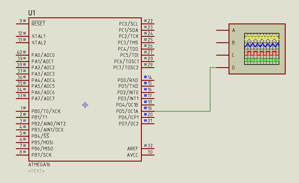
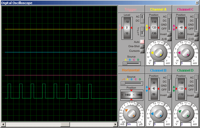
The results of the simulation of the circuit in the PROTEUS programSchematic diagram of a TB signal generator

The baby of the hand-me-down pay

This sampler can generate five pictures, which is sufficient for re-verification and repair of small, personnel cuts of the TV set, regulation of the performance and geometric patterns of the raster, color balance, control of the passage of signals along the channels of the TV set. With a short-time pressure on the button, the wines are thrown and start to generate the next picture, with an offensive pressure on it, the pictures are moving over the stake. When the button is pressed, at the moment the generator is released, it will switch to sleep mode. Also, it will automatically switch to the sleep mode, if there are more than 5 whilins of switching on. 
Archives are added to the article, in which there is a circuit, a probe board, two firmware. On the video you can see that the picture on my TV set is not linear - it’s the same as the TV set has 12 years, and maybe it’s not the same at the entrance.
The generator is connected to the TV's video input, sound like "tulip" or "SCART"
Appliance generating six fields:
- text field of 17 rows;
- mesh 8x6;
- mesh 12x9;
- another checker's field 8x6;
- large checker's field 2x2;
- White field.

- clock frequency - 12 MHz;
- voltage of life 3 - 5 V;
- Strumming in working mode:
- at a voltage of 3V - close to 5mA;
- at a voltage of 5V - close to 12mA;
- frame rate - 50 Hz;
- Number of rows per frame - 625. 
The scheme is rather simple.
All work from forms
video signal
beaten by the program,
sewn in microcon-
troller. Two resistors
together with support
TV video input
take care of the necessary
my equal voltages
video signal:
- 0 V - synchronization;
- 0.3 V - black rhubarb;
- 0.7 V - rіven gray;
- 1 V - rіven white.
3V ... - R5 = 456Ω and R6 = 228Ω
3.5V - R5 \u003d 571 Ohm and R6 \u003d 285 Ohm
4V ... - R5 = 684Ω and R6 = 342Ω
4.5V - R5 \u003d 802 Ohm and R6 \u003d 401 Ohm
5V...- R5=900Ω and R6=450Ω
Here the meaning of the Rozrahunka is indicated. In reality, you can put resistors in the standard row, for example, for 5V - 910 Ohm and 470 Ohm, and for 3V - 470 Ohm and 240 Ohm.
Generator voltage may be less than 3V. For skin-specific PIC, the minimum should be determined experimentally. I, for example, have a 20MHz PIC release in 2001 for 2.3 Art.
Program form 6 fields. The skin field is composed of 301 rows (300 informational rows + one black). The number of shots is 305 (625 rows in the raster - 15 rows in frame synchronization = 610. The information in the frame is displayed through the row (see here for more details), tom 610/2 = 305). But with such a number of rows, the raster is expanded vertically, there are three more for those that form the video signal, broadcasts by the television center.
The first row in skin polychryonium. At this hour, the station of the button S2 is being used, the hour of morning in the pressed station is calculated, and the need to move from one field to the next is indicated.
The graphic fields have small curvature of the vertical lines. For this reason, the number of the last rows is a couple of cycles longer than the others due to the need to install the lichnik cycles. In general, the programs that form the graphic fields are even simpler, so there is no need to comment.
Let's talk about that part of the program that forms the text field. This is the best place for programs that take up the largest part, the maximum resource of the microcontroller (all the memory of these is a significant part of the RAM). Here are some code snippets taken from Gri Pong by Rickard Gunee.
The text field can be stacked up to 17 rows, leather can stack up to no more than eight characters. Symbols are displayed through a row, so one row of the text takes up 17 rows of the raster. (This is due to the PIC's limited capabilities.) Information about the character schedule is stored in the program memory of the distribution table. Information about the text of the row is taken from the memory of the data (64 words = 8 rows of 8 characters). For example, in row 08h (addresses from 08h to 0Fh) is written forward: 20.60.48.50.90.58.20 Value.20. confirming the test, .60. - letter "B", .48. - letter "I", and so on. And all at once I make "_VIDEO".
Let's take a look at the butt, how to display the text. Depending on the program, at the 12th text line of the screen, it is necessary to enter information, so that the data memory line 28h is required (A0 B8 68 C8 D8 70 E0 D0). In this rank, in the next 17 rows of the raster, the text can be seen: "pic 1 6 f 8 4". Seems so. The first of 17 rows has an extra black rive. In qi 64 µs, while the black row is displayed on the screen, the RAM registers are overwritten by the "upper values" of the symbols: 00h.vіd "p", 08h vіd "i", 00h vіd "c" 18h vіd "1" and so on. Under the hour of the next row, the data are sequentially transmitted to PORTB, so the video output. The third row is again black. For an hour її vykonannya, the buffer is rewritten "other beasts" character values: 00h.vіd "p", 00h vіd "i", 00h vіd "c" 1Ch vіd "1"... In the fourth row, data are displayed on the screen. And so on, until the whole row is brought out.
The HR Synchronization Subprogram is taken from Gri Pong by Rickard Gunee. Tsya subprogram is short, but it is confused. How to explain, how it works, you see more better and more confused. It is best to put a text instructed by subprograms and small oscillograms of personnel sync pulses, and do not hurry to sort out the skin row to the code. I will only say that the subprogram starts not from the top row, but from the middle (:-)), like the "vertsync" mark.
As can be seen from the diagram in this project, the microcontroller operates at a frequency of 12 MHz. Today, three versions of the PIC16F84 are released: at 4MHz, at 10MHz, and at 20MHz. (As of 1.1.2002, the price changes were approximately the same: $3.5, $5.3 and $6.3) In his project Pong Rickard Gunee, he confirmed that the 4 MHz PIC16F84 victorious and worked for years at a frequency of 12 MHz without problems. I tried, and indeed the 4MHz PIC normally works on the frequency, as if twice (!!!) exceeds the permissible frequency (although I didn’t try the fraction and turned on the generator less than a sprat of whilin). At 4MHz PICA, the strum rate is 10...20% higher, lower at 20MHz (sounds, maybe even lowering by frequency). I think that a 10 MHz microcontroller can be expanded up to 12 MHz without a risk, but in commercial projects, which, obviously, does not work well.
1. Attiny2313 microcontroller - 1 pc.
2. RK indicator WH0802 or HD44780 sum - 1 pc.
3. Chip LM324 - 1 pc.
4. Clock buttons without fixation - 3 pcs.
5. Resistor 10 kOhm - 1 pc.
6. Resistor 300 Ohm - 1 pc.
7. Resistor 2 kw - 8 pcs.
8. Resistor 1 kw - 9 pcs.


List of radio elements
Appointment
Type
Denomination
Kіlkіst
Note Score My notepad
U1
MK AVR 8-bit 1
Do notepad
U2
Operational helper 1
Do notepad
R1-R8
Resistor 8
Do notepad
R9-R16, R18
Resistor 9
Do notepad
R17
Resistor 1
Do notepad
R19
Resistor 1
Do notepad
BTN1-BTN3
Button Without fixation 3


