Delta Loop (either a tricout antenna or a simple bagatodi-band antenna or an Antenna HF Delta). Antenna vertical Delta Loop Antenna delta per square
Antennas are short
Practical designs of amateur radio antennas
The branch has a large number of different practical designs of antennas and other satellite outbuildings. To make it easier to ask, you can click on the button “View the list of currently published antennas”. More on topics - div. CATEGORIES (CATEGORY) with regular updates of new publications subtitles.
Dipole with a living point displaced in the center
Bagatioh korotkohvilyovikіv tsіkavlyat simple HF antennas, which will ensure without any commutations the robot on many amateur bands. Find a similar antenna - Windom with a single-wire feeder. But the price for the simplicity of the preparation of the antennas is boules, and they are inevitably lost when a single-wire feeder is used to switch televisions and radio communications and the satellite connection of the satellites from the susides.
The idea of Windom-dipoles is quite simple. By changing the point of life in the center of the dipole, you can know the same sp_v_dnoshnenya of the shoulders of the shoulders, at which the entrance supports in a number of ranges become close. Most often they joke about the difference, at which it is close to 200 or 300 ohms, and the use of low-resistance cables is based on additional symmetrical transformers (BALUN) with a transformation ratio of 1:4 or 1:6 (with a cable with a 50-ohm support). The very same vikonanі, for example, antennas FD-3 and FD-4, yakі let out, zokrema, serially in Nіmechchinі.
Radioamators design similar antennas independently. Pevnі trudnoshchi, schopravda, blamed for the preparation of symmetrical transformers, zocrema, for work in the entire short-wave range with vikoristanny tension, which exceeds 100 watts.
A serious problem is those that such transformers normally work only on the basis of the need. And in this case, the mind does not seem to be viable - the input opir of similar antennas is actually close to the required value of 200 or 300, but it can be seen in them, moreover, on all ranges. The legacy of this is that such a design saves the antenna effect of the feeder, regardless of the constriction of the narrow transformer and the coaxial cable. І as a result of the change in antennas of symmetrical transformers, it is possible to achieve a folding design without causing a new TVI problem.
Oleksandr Shevelyov (DL1BPD) away, zastosovuyuchi uzgodzhuvalnі podstroi on lines, razrobiti variant uzgodzhennia Windom-dipoles, yak vikoristovuyut zhivleniya via coaxial cable and liberated tsgogo nedolіku. About them rozpovidalos in the magazine "Radioamator. Bulletin of the SRR” (2005, birch, p. 21, 22).
How to show rozrahunki, the best result is to go to the lines with fluted supports 600 and 75 Ohm. A line with a 600 ohm windshield supports the antenna input on all operating bands of approximately 110 ohms, and a 75-ohm line of this opir transforms to a value close to 50 ohms.

Let's look at a variant of such a Windom-dipole (range 40-20-10 meters). On fig. 1 pointing to the back of the shoulders and line dipoles in tsikh ranges for darts with a diameter of 1.6 mm. The length of the antenna's length is 19.9 m. A line with a soft support of 600 Ohm is connected to the new line and a length of approximately 1.15 meters, and a coaxial cable with a soft support of 75 Ohm is connected to the end of the line.
Remaining at a shortened cable coefficient, which is K = 0.66, may be 9.35 m. For such dimensions, the antenna is optimized for operation in swags of frequencies 7 ... 7.3 MHz, 14 ... 14.35 MHz and 28 ... 29 MHz (with a minimum SWR at a frequency of 28.5 MHz). Rozrahunkovy graph of SWR of the antenna for the installation height of 10 m is shown in fig. 2.

Using a cable with a 75 ohm fiber support in this case is not the best option. Lower SWR values can be obtained by stopping the cable with a 93 ohm pole or the line with a 100 ohm pole. Її can be prepared from a coaxial cable with a 50 ohm cable support (for example, http://dx.ardi.lv/Cables.html). If it is installed with a line with a 100 Ohm fluffy support for a cable, turn on BALUN 1:1 on the її end.
To change the level, the transition from a part of the cable with a fluffy support of 75 Ohm is followed by a choke - a coil (bay) Ø 15-20 cm, to cover 8-10 turns.
The directivity diagram of the antenna is practically not affected by the directivity diagrams of a similar Windom-dipole with a balanced transformer. Її KKD is to blame for the worse, lower antennas with BALUN switches, and the adjustment - not more folding, lower adjustment of the great Windom-dipoles.
vertical dipole
It is good to know that for robots on distant routes, a vertical antenna can be overwhelmed, so the straightness diagram in the horizontal plane is circular, and the head pan is pressed to the horizon by the diagrams near the vertical plane and may be slightly vibrated in the zenith.
Proper preparation of vertical antennas is due to low design problems. Zastosuvannya aluminum pipes as a vibrator and the need for effective work to install in the basis of the "vertical" system "radial" (opposite), which is made up of a large number of darts a quarter of a whil. How to beat a vibrator like a vibrator is not a pipe, but a wire, a shoe that supports it, is guilty of vikonana z dielectric and all the connections, which support a dielectric box, also dielectric or break on non-resonant insulators. Everything is connected with windscreens and often impossibly constructively, for example, through the necessary space for placing the antenna. Don't forget that the input opir of the "verticals" sound lower than 50 ohms, and even more so with the feeder.
On the other side, horizontal dipole antennas, up to which it is possible to carry antennas of the Inverted V type, are structurally simpler and cheaper, which explains their popularity. The vibrators of such antennas can be practically used for any purpose, and the shoes for their installation can be prepared from any material. The input opir of horizontal dipoles or Inverted V is close to 50 ohm, and you can often get by without additional support. The directivity diagrams of the Inverted V antenna are shown in fig. one.

Up to a few horizontal dipoles, one can see a non-circular straightness diagram near the horizontal plane and a great wind deflection curve near the vertical plane, which is more important for work on short routes.
The primary horizontal rotating dipole is rotated vertically by 90 degrees. and it is an omnipotent vertical dipole. For changing yoga dozhini (at different heights), the victorious solution is “a dipole with curved ends”. For example, a description of such an antenna is in the files of the library I. Goncharenka (DL2KQ) to MMANA-GAL program - AntShortCurvedCurved dipole.maa. Vіdginayuchi part of vibrators, mi, zvichayno, vtrachayemo in strong antennas, but it is also important to play in the necessary hight chugli. Vіdіgnutі kіntsі vіbratorіv vіbratorіv оnly raztashovanі one over one, vіdіgnutі vіdіnіvannya kolіvіvanі іz horizontal polarization, shіdlіvі vіpadku. Eskіz zaproponovanogo variant of the antenna, called the Curved Vertical Dipole (CVD) by the authors, representations in fig. 2.

Pochatkovі mind: a dielectric shugla with a height of 6 m (scleroplast or a dry tree), kіntsі vibrators with a dielectric cord (little fox or kapron) under a small kut to the horizon. The vibrator is prepared from a middling rod with a diameter of 1-2 mm, bare or in insulation. At the points of evil, a vibrator was attached to the pins.
It is easy to notice that through the shortening of the dipole of the CVD antenna dipole, it can be 5 dB less strong, but when the wind speed is 24 degrees. (Maximum CVD gain) difference is only 1.6 dB. In addition, the Inverted V antenna may be uneven in the directivity diagrams in the horizontal plane, which reaches 0.7 dB, so in some direct directions it won out in CVD strength of only 1 dB. Shards of rozrahunkov's parameters of both antennas turned out to be close, the residual visnovka could help to build an experimental reverification of CVD and a practical robot on the air. Three CVD antennas were prepared on the range of 14, 18 and 28 MHz for the sizes shown in the table. All of them are small for the same design (div. small. 2). The dimensions of the upper and lower arms of the dipole are the same. Our vibrators were wired from the P-274 field telephone cable, and the insulators were from the orgskla. The antennas were raised on a 6 m scleroplasty frill, and the upper point of the skin antenna was at a height of 6 m above the ground. The broken parts of the vibrators were pulled with a kapron cord from a point of 20-30 degrees. to the horizon; The authors changed their minds (therefore confirmed and modeled) that they made 20-30 deg. practically not b'є according to the characteristics of CVD.
Modeling in the MMANA program shows that such a vertical dipole can be easily used with a 50 ohm coaxial cable. Vіn maє maє kut vprominyuvannya near the vertical plane and the circular straightness diagram near the horizontal (Fig. 3).

Structural simplicity made it possible to change one antenna for another by stretching five quills around the dark. For livelihood of all CVD options - antennas are victorious with the same coaxial cable. Vіn approaching the vibrator under the hood is close to 45 degrees. To stifle the common-mode stream, order from the point of connection to the cable the installation of ferrite magnetic conductor tubing (filter-drying). A sprat of similar magnetic conductors should be installed on a distance of 2 ... 3 m to the winding cable near the antenna canvas.
Antenna shards were made from "watering", and the insulation approximately 1% increased the electrical power. Therefore, the antennas, prepared for rozmіrami, pointing in the tables, required some speed. The construction was carried out to regulate the bottom of the lower concave vibrator, easily accessible from the ground. Having combined a part of the lower part of the lower bent dart in half, you can work a thinner substroying of the resonant frequency, passing the end of the bent log to the drota (its own train of the substroying).
The resonant frequency of the antennas was measured with an antonym analyzer MF-269. All antennas had a small minimum of SWR at the borders of the amateur bands, without exceeding the value of 1.5. For example, for an antenna on the 14 MHz band, the minimum SWR at a frequency of 14155 kHz is 1.1, and the bandwidth is 310 kHz for an SWR of 1.5 and 800 kHz for a SWR of 2.
For equal vibratory tests, the Inverted V band of 14 MHz was installed on a metal box with a height of 6 m. The vibrators were at a height of 2.5 m above the ground.
In order to evaluate the objective assessment of the level of signals in the minds of QSB, the antennas of the bagatatoria chirped from one to the other with the hour of the chime for no more than one second.
table

We carried out radio communication in SSB mode for transmission of 100 W on routes with a length of 80 to 4600 km. On the 14 MHz band, for example, all correspondents who were more than 1000 km away indicated that the signal from the CVD antenna was equal to one or two points higher, lower than Inverted V. When the distance was less than 1000 km, Inverted had a minimum gain V.

Testing was carried out during a period of poor minds passing radio waves on the HF bands, which explains the presence of more distant calls.
During the period of ionospheric passage in the range of 28 MHz, we carried out our QTH with a radio antenna in the surface fluff with Moscow short-waves for about 80 km. On a horizontal dipole, it was almost impossible to wind a troch above the CVD antenna, none of them could be.
The antenna is made from cheap materials and does not require a lot of room for placement.
When vikoristannі like pulling kapron hair out, you can masquerade as a whole under the flagpole (cable, broken on the plots of 1.5 ... cottages (Fig. 4).
Files in the .maa format for independent verification of the power of descriptions of antennas are found.
Vladislav Shcherbakov (RU3ARJ), Sergiy Filippov (RW3ACQ),
m Moscow
It is proposed to modify the T2FD with a rich antenna, as it allows to block the entire range of radio amateur HF frequencies, which is similar to the low-profile dipole in the 160-meter range (0.5 dB on the near and close to 1.0 dB on the DX routes). With an exact repetition, the antenna should be repaired in a row and repair is not required. The peculiarity of the antenna is noted: static transitions are not accepted, and they are paired with the classic naive dipole. At such a vikonan, the reception of the ether comes out to be comfortable. Only weak DX stations can be heard normally, especially in the low-frequency bands.
Three years of operation of the antenna (more than 8 years) allowed us to deservedly bring it to low-noise receiving antennas. In other words, for efficiency, this antenna is practically not compromised by a range-type dipole or an Inverted Vee on any of the ranges from 3.5 to 28 MHz.
And one more warning (based on the reports of distant correspondents) about the hour of making a call during the day, deep QSB. From 23 variants of modifications of antenna numbers, proposed here, merit for special respect and may be recommendations for mass repetition. All proponovanie expansion of the antenna-feeder system is insured and exactly vivirenі in practice.
Anteni cloth
Razmіri vibrator induced little. The halves (offenses) of the vibrator are symmetrical, the seal of the dozhin of the “internal kuta” is hurried to the place, and there is also a small maidanchik (obov'yazkovo insulating) for the protection of the line of living. Balancing resistor 240 ohms It is also possible to vikoristovuvat whether it is some other resistor of tension, smut, schob opir bov obov'yazkovo non-inductive. Midny drіt - in isolation, 2.5 mm peretina. Rozpіrki - wooden slats in rosrіzі with peretina 1x1 cm with lacquer coating. Vіdstan mіzh otvorіvnyuє 87 cm.
Povіtryana line of life
For line zhivlennya zastosovuєmo midny drіt PV-1, peretina 1mm, rosettes of vinyl plastic. Vіdstan between conductors to become 7.5 cm. The length of all lines is 11 meters.
Author's version of the installation
Zastosovuєtsya metaleva, grounded from below, shugla. The hood is installed on a 5-surface booth. Chogla - 8 meters with pipes Ø 50 mm. Kіntsi antennas are placed for 2 m from a distance. Uzgodzhuvalny transformer core (SHPTR) is prepared for TVS-90LTs5 charging transformer. The coils are gone there, but the very core of the gluing with the “Supermoment” adhesive becomes a monolithic steel with three balls of varnish fabric.
The winding is wound into 2 darts without twisting. The transformer contains 16 turns of a single-core insulated copper wire Ø 1 mm. The transformer has a square (and straight-cut) shape, so 4 pairs of turns are wound on the skin from 4 sides - the best option for a streak.
The SWR in the whole range goes from 1.1 to 1.4. ShPTR vengeance in the goodness of soldering with a braid of a feeder a screen with a coat. From the inner side to the new superficially solder the middle winding of the transformer winding.
After folding and installing the antenna, it is practicable in time and practical in any minds, so that it is roztashovuyuchis low above the ground, or above the house a booth. Vaughn may even be a low TVI rіven (television reshkod), and ce dodatkovo can zatsіkaviti radioamatorіv, scho work out of the forces or dacha residents.
Antenna Loop Feed Array Yagi for the range of 50 MHz
 Antennas Yagi (Yagi) with a frame vibrator, ruffled at the antenna plane, are called LFA Yagi (Loop Feed Array Yagi) and are characterized by a larger, lower in the loudest Yagi operating frequency range. One of the most popular LFA Yagi is Justin Johnson's (G3KSC) 5-piece 6-meter band design.
The scheme of the antenna, between the elements and the difference between the elements, is shown below in the table and on the armchair.
Elements are installed on a traverse with a length of about 4.3 m from a square aluminum profile with a cross-section of 90 × 30 mm through insulation. The vibrator is powered by a 50-ohm coaxial cable through a balanced transformer  1:1.
1:1.
Adjusting the antenna for the minimum SWR in the middle of the range is carried out by choosing the position of the end P-like parts of the vibrator from tubes with a diameter of 10 mm. It is necessary to change the position of these inserts symmetrically, so that if the insert was hung 1 cm to the right, then it is necessary to hang it on the insoles.
SWR meter on male lines
 Widely known from the radio amateur literature of SWR-meters and vikoraniya s vikoristannyam directing vodgaluzhuvachіv and є odnosharovymi.
  a coil or a feritic kіltsevy core with a kіlkom with coils of drotu. Appointed attachments may have a number of shortcomings, the main ones are those that, in the presence of great strains, are high-frequency "guided" at the miraculous lance, which leads to additive vitrates and zusil on the screen of the detector part of the SWR meter to change the formal radioamator until ready to attach, the SWR meter can cause a change in the cable support of the feeder line in the fallow frequency. Proponations of the Uva KSV-meter on the basis of the interagencies of the stagnation of VіdgalhivAvachiv, constructively wicked by the Visigands of Oblast Self-Safety Poilant II Dzvololi Visnochiti Vizyudnya and Vіdbitoi Movil in Lancer Antenna at Luzuyti, Shaho pivot to 200 W in the frequency dіapanі 1 ... 50 MHz soft support 50 Ohm. Yakschko Potterbno Mati Tіlki індикатор VihIMI Wheel Passion Transmission of Abo Control by Struz Antenna, it is possible to sniffing such an attachment: with Vimіranuvanі KSV in Lynіyah z Khvilov's support to Vіdmіnnim Vіd 50 ohms, a sign of resistorіv R1 І R2 Slіd Zmіniti to the magnitude of the Cyville Support.
The design of the SWR meter
 SWR meter on a plate made of double-sided foil-coated PTFE with a thickness of 2 mm. As a replacement for a double-sided sklotekstolit.
The line L2 of the vikonan on the right side of the board is shown as a lean line. Size 11 x 70 mm. In open the lines L2 under the roses XS1 and XS2, there are inserts, like flaring and soldering together with L2. The hot tire on both sides of the board may have the same configuration and is shaded on the scheme of the board. At the tops of the dress, drilled holes are opened, in the yaks, a dart with a diameter of 2 mm is inserted, soldered from both sides of the hard tire. Lines L1 and L3 are stitched from the front side of the dress and can be cut: a straight section 2 × 20 mm, between them 4 mm and stitched symmetrically to the later axis of line L2. Zsuv mіzh them vzdovzh posterior axis L2 -10 mm. All radio elements are stitched from the side of the strip lines L1 and L2 and soldered with an overlap without a middle to the other conductors of the SWR-meter board. Other guides pay the next time. The selected board is soldered without intermediary to the contacts of the sockets XS1 and XS2. Zastosuvannya dodatkovyh 'dnuvalnyh conductors or coaxial cable є unacceptable. Ready SWR-meter is placed near the box with non-magnetic material of the machine 3...4 mm. I’ll pay the spherical bus for an SWR meter, the body will attach and the roses will connect electrically between itself. In case of SWR change in the coming order: at the S1 “Straight” position, for the help of R3, set the microammeter needle to the maximum value (100 μA) and change S1 to “Zvorotna”, reset the SWR value. With the help of the indication of 0 μA, the SWR is 1; 10 µA - SWR 1.22; 20 µA - SWR 1.5; 30 µA - SWR 1.85; 40 µA - SWR 2.33; 50 μA - SWR 3; 60 μA - SWR 4; 70 µA - SWR 5.67; 80 µA - 9; 90 µA - SWR 19.
Nine-band HF antenna
Antenna is a different type of multi-band antenna "WINDOM", in which the living point is located in the center. At the same input of the antenna in dekilkoh amateur bands KB to become approximately 300 ohms,  which allows you to twist as a feeder and a single wire, and a double-wire line with a double-width support, and, nareshti, a coaxial cable, which is connected through an uzgodzhuvalny transformer. In order for the antenna to work in all nine amateur KB bands (1.8; 3.5; 7; 10; 14; 18; 21; 24 and 28 MHz), in parallel, essentially two WINDOM antennas were switched on (div. a): one of the deep valleys is about 78 m (l/2 for the 1.8 MHz band), and the other is about 14 m (l/2 for the 10 MHz band and l for the 21 MHz band). Obidva viprominyuvachi live in one coaxial cable with a 50 ohm support. Uzgodzhuvalny transformer maє coefіtsієnt transformation support 1:6.
Zrazkove roztashuvannya viprominuvachіv antennas in the plan is shown in fig. b. 
When the antenna is installed at a height of 8 m above the ground, conduct a standing wind coefficient in the range of 1.8 MHz without exceeding 1.3, in the ranges of 3.5, 14. 21, 24 and 28 MHz - 1.5, in the ranges of 7. 10 and 18 MHz - 1.2. In the ranges of 1.8, 3.5 MHz and the world in the range of 7 MHz, with a height of 8 m, the dipole, as it seems, seems to be mainly under the great kutas to the horizon. Also, at times, the antenna will be more effective for short-range calls (up to 1500 km).
The connection diagram of the windings of an uzgodzhuval transformer for the selection of a transformation ratio of 1: 6 is shown in fig.

Windings I and II may have the same number of turns (like a primary transformer with a transformation ratio of 1:4). If the number of turns of these windings is higher (and it should lie in front of the opening of the magnetic circuit and the first magnetic penetration) is more than n1, then the number of turns n2 at the starting point of the windings I and II before the introduction is calculated according to the formula 8 n2.t.
 Horizontal frames are more popular. Rick Rogers (KI8GX) conducted experiments with a frail frame, which can be fastened to one pinch.
For the installation of a “poor frame” with a perimeter of 41.5 m, a balaclava with a height of 10 ... 12 meters and an additional support of the wreath of about two meters are required. Up to tsikhl the protelezhnі kuti frames are fastened, which makes the shape of a square. Vіdstan mіzh stubbles are chosen so that they cut the frame on the ground by extending to the ground at the borders of 30 ... 45 °. The point of life of the frame is ruffled at the upper edge of the square. Live frame coaxial cable іz hvilyovim support 50 Ohm. Behind the KI8GX vims, in this variant, the frame is small SWR = 1.2 (minimum) at a frequency of 7200 kHz, SWR = 1.5 (to achieve a “stupid” minimum) at frequencies higher than 14100 kHz, SWR = 2.3 in the entire range of 21 MHz, SWR = 1.5 (minimum) at 28400 kHz. At the edges of the ranges, the PKC value did not exceed 2.5. Following the author's tribute to the deaco of increasing the scope, move the frame at least closer to the telegraph stations and allow the SWR to be less than 2 at the boundaries of the operating bands (crim 21 MHz).
QST №4 2002 rіk
Vertical antenna for 10, 15 meters
 A simple combined vertical antenna for the ranges of 10 and 15 m can be built both for work in stationary minds, and for foreign flights. The antenna is a vertical vibration monitor (Fig. 1) from a filter (ladder), which is fenced, and two resonant counters. Ladder for the selected frequency in the range of 10 m, to that in the same range of vibrance is the element L1 (marvelous figure). In the range of 15 m, the inductance coil of the ladder is to be lowered and combined with the L2 element (div. babies) to bring the head length of the viprom_nyuvach to 1/4 of the length of the fluke on the range of 15 m. fixed on fiberglass pipes. "Trapova" antenna is less "capricious" for the improved operation, the lower antenna, which consists of two hand-stitched instructions for viprominuvachiv. Antennas are shown in Figure 2. Viprominyuvach is made up of a number of duralumin pipes of various diameters, connected one by one through the transition bushings. Live antenna 50-ohm coaxial cable. To protect the HF strum on the outer side of the braided cable, the life is built through the strum balun (Fig. 3), the strum on the ring core FT140-77.
  The winding is made up of four turns of the RG174 coaxial cable. The electrical capacity of this cable is sufficient for work with transmission of up to 150 watts. When working with a larger forceful transmission, either a cable with a Teflon dielectric (for example, RG188), or a cable of large diameter, for winding it, naturally, needs a ferrite ring of a wide diameter. The balun is installed at the second electric box:
It is recommended to install a non-inductive doubling resistor with a support of 33 kOhm between a vertical viprominuvachem and a support pipe, on which an antenna is attached, which will help accumulate a static charge on the antenna. The resistor is manually placed in a box, where a balun is installed. The design of the ladder can be whatever.
So, the inductance coil can be wound on a PVC pipe with a diameter of 25 mm from a wall thickness of 2.3 mm (the lower and upper parts of the viprominuvach are inserted at the pipe). Cotushka revenge 7 turns of a copper dart with a diameter of 1.5 mm for varnish insulation, wound with a croc of 1-2 mm. The required inductance of the coil is 1.16 μH. A high-voltage (6 kV) ceramic capacitor with a capacity of 27 pF is connected in parallel to the coil, and as a result, a parallel kolyvalny circuit operates at a frequency of 28.4 MHz.
More precisely, the adjustment of the resonant frequency of the circuit is carried out by squeezing and tightening the turns of the coil. If the coils are fixed, they are fixed with glue, and then there is a trace of the mother on the uvaz, which the overworld amount of glue applied to the coil can significantly change the inductance and increase the dielectric inputs and, obviously, lower the KKD of the antenna. In addition, the ladder can be made from a coaxial cable, winding 5 turns on a PVC pipe with a diameter of 20 mm, and it is also necessary to transfer the ability to change the winding angle to ensure accurate tuning to the required resonant frequency. The design of the ladder for yoga rozrahunka can be manually downloaded using the Coax Trap program, which can be obtained from the Internet.
Practice shows that such ladders can be successfully produced from 100-watt transceivers. For the protection of the ladder, inflowing into the navkolishny middle of the veins, it is placed near a plastic pipe, like a beast, it is closed with a stub. Opposites can be made from an uninsulated dart with a diameter of 1 mm, and they can be separated evenly one type of one. As for the countermeasures, it is necessary to conduct a wire at the plastic insulation, shorten the trace of the troch. Thus, counters with a mid-range dart with a diameter of 1.2 mm and a vinyl insulation with a thickness of 0.5 mm are due to a mother of 2.5 and 3.43 m for ranges of 10 and 15 m.
The tuning of the antennas is repaired at a range of 10 m, having shifted forward, so that the ladder is adjusted to the selected resonant frequency (for example, 28.4 MHz). The minimum SWR at the feeder is reached by the lower length (to the ladder) of the viprominuvach. If this procedure turns out to be unsuccessful, then it happens that in the small boundaries you change the kut, under which the opponent is roztashovuetsya shdo viprominyuvacha, the dozhina of the opponent and, perhaps, yogo roztashuvannya in space. Only a few of them are taken for the installation of antennas in the range of 15 m. It’s impossible to get a good SWR, so after fixing the solution, it’s recommended to adjust the antenna in the range of 10 m.
Adjustment of the antenna and contours for the auxiliary generator of the shift code
For robots with this alternator circuit, it is possible to switch relays of any type with a high-voltage voltage and with a normally closed contact. If the voltage is higher than the voltage of the relay, then the voltage is higher, the voltage is changed by the generator. To change the level, aim at the outbuilding, which is to be tested, it is necessary to seriously shut down the generator, and revitalize the batteries or the battery to prevent the overshoot at the fence. Let's look at the adjustment of the switching protection of the outbuildings, with such a switching generator it is possible to carry out the simulation and adjustment of the high-frequency equipment and її nodes.
Designation of the resonant frequency of the circuits and the resonant frequency of the antenna

 In case of varying the look-back priming with an uninterrupted range or hvilemy, it is possible to assign the resonant frequency of the circuit for the maximum level of switching on the output of the priming or hvilemy. For the use of the generator and the priming on the parameters of the circuit їх coil, the connection is due to the mother, the minimum possible connection with the circuit. When the generator is connected, the transition to the antenna WA1, which is being tested, can be similarly to the vimiryuvannya circuit, you can choose the resonant frequency or frequency.
I.Grigoriv, RK3ZK
Wide range aperiodic antenna T2FD
 Pobudov’s antennas at low frequencies at the link with great linear distances called out at the radioamators with a lot of difficulties, due to the time necessary for the open space, folding and preparation of the installation of high chocolates. That is why, practicing on surrogate antennas, it is rich in vicory cikavi low-frequency bands, mainly for radio calls, with a sound "a hundred a kilometer".
The amateur radio literature has inventories of effective vertical antennas, which, according to the authors, practically do not occupy the area. Ale varto guess what a significant space is needed for the deployment of an anti-aircraft system (without any vertical antenna є ineffective). For this reason, the occupied area needs to be lined with line antennas, especially for the popular “inverted V”, which requires only one card for them. However, the transformation of such an antenna into a two-band richly larger area, so that it is necessary to place it in different areas in different bands.
Spratobi Vikrotovati Elementi, Scho Permanent, Settlement of Lynі My Livestone, TDDRIK TRADE RTrevnia RTDDRIZE (on the available viscos of 12-20 meters) to win Naisstіshe to the SUPERSURROGATIV Witrerrogatіv, you can spend the vigilance of your nervous system.
The proponated antenna is not “defective”, but it allows normal operation in two or three bands without any flickering, it maintains the stability of the parameters and does not require a fine tuning. Mayuchi high entrance opir at low altitudes, it will ensure the best efficiency, lower simple drotyany antennas. Tse trohi is widely modified T2FD antenna, popular for example 60s, unfortunately, none of them can be found. Obviously, she got into the category of “zabutih” through a resistor, which sheds light on, on which up to 35% of transmission tightness is increased. If you are afraid to spend a lot of money, if you want to use T2FD with a non-serious design, you want to calmly win on the HF bands with a stir with a trio of counters, efficiency. do not force anyone to "dotyaguє" up to 30%. It happened to be almost faceless "against" a poorly proponated antenna, often not primed with anything. I'll try briefly viklasty tі "for", zavdyaki bulo collected T2FD for work on the low bands.
In the aperiodic antenna, which is in the simplest variant a conductor with a winding support Z, the windings on the support of Rh=Z, falling winds, having reached the winding of Rh, do not reappear, but rather fade. Zavdyaki why the mode of sickness is being restored, what to live, for which the steel of the maximum value of the struma Imax is characteristic of the conductor. On fig. 1(A) shows the strumming of the ventilated vibrator, and in fig. 1(B) - allow the antenna to be wounded, to live (spend on the repair and in the conductor of the antenna is not mentally protected.
Theoretically, the antenna is understood to be an effective (electrical) antenna, as it is determined by the replacement of a real vibrator, we will reveal that the frequency of which strum is distributed evenly, may also be the value of Imax, which is the same for the final vibrator (as in Fig. 1 B). The length of the oscillating vibrator is chosen such that the geometrical area of the real vibrator's struma equals the geometrical area of the oscillating one. For a nap_vilovogo vibrator, the length of the visible vibrator, if the area of the struma is equal, set the value equal to L / 3.14 [pі], de L - the length of the fluff in meters. It does not matter if the length of the double-width dipole with geometric dimensions = 42 m (range 3.5 MHz) is electrically equal to 26 meters, if it is the effective length of the dipole. Turning back to small. 1(B), it is easy to see that the effective aperiodic antenna base is practically the same as the geometric base.
Conducted experiments in the range of 3.5 MHz make it possible to recommend this antenna to radioamators as a good option "vitrati-widdacha". An important advantage of T2FD is its wide range and practicality at “ridiculous” height ranges for low frequency ranges, usually from 12-15 meters. For example, the dipole of the 80-meter range, with such a height, is transformed into a "viysk" anti-aircraft antenna,  because viprominyuє uphill is close to 80% of the reduced tension. The main dimensions and design of the antenna are shown on the small.
Vikonati transformer can be practical on any magnetic circuit with a penetration of 600-2000 PN. For example, the core of TVS of lamp televisions or a pair of folded rings at once with a diameter of 32-36 mm. Winding three windings, winding two darts, for example MGTF-0.75 sq. mm (winning by the author). Peretin lie down in the tightness, which is brought up to the antenna. Carry out the windings stacked schіlno, without crochet and twists. At the place indicated in Fig. 4, the darts should be crossed.
Finish winding 6-12 turns at the skin wrap. If you carefully look at Fig. 4, then the preparation of the transformer does not mean everyday difficulties. The core should be protected with corrosion varnish, oily and water resistant glue. A cladding opir can theoretically predict 35% of the tension that can be applied. It has been experimentally established that the MLT-2 resistors vibrate 5-6-fold switching over the frequency of the constant stream at frequencies of the KB range. With an intensity of 200 W, 15-18 MLT-2 resistors are sufficient, connected in parallel. The resulting opir may be in the range of 360-390 ohms. Z assigned in Fig. 2 the dimensions of the antenna are used in the ranges of 3.5-14 MHz.
For work in the 1.8 MHz band, it is necessary to increase the antenna length, if you want up to 35 meters, ideally 50-56 meters. With the correct tuning of the transformer T, the antenna, no matter how installation is required, it is necessary to change the fact that the SWR lies in the range of 1.2-1.5. Otherwise, pardon next shukati at the transformer. It should be noted that with a popular 4:1 transformer based on a long line (one winding for two darts) of the antenna robot, it drops sharply, and the SWR can be 1.2-1.3.
German Quad Antenna for 80, 40, 20, 15, 10 and cast 2 m
Most of the Russian radioamators are faced with the problem of placing a short-wave antenna through the space.
But if there is a place for hanging a dart antenna, then the author encourages him to speed up and build the GERMAN Quad /images/book/antenna. Vіn podomlyaє scho won't work well on 6 amateur bands 80, 40, 20, 15, 10 and navit 2 meters. The antenna scheme is shown in the figure. For її preparation it is necessary exactly 83 meters of honey darts with a diameter of 2.5 mm. The antenna is 20.7 meters square with a side of 20.7 meters, which moves horizontally at a height of 30 feet - approximately - 9 m. The line works well with a 75 ohm coaxial cable. For the author's advice, the antenna may have a strength of 6 dB for a dipole. At 80 meters, you can achieve a high kuti viprominyuvannya and good practice on the distance of 700 ... 800 km. Starting from the 40-meter range, the vibrations at the vertical plane change. On the horizon, the antenna has no other priorities for directing. Її the author promotes vicariously and for mobile-stationary work in the minds of the sexes.
3/4 long wire antenna
 Most of the yogo dipole antennas are based on the double hair of 3/4L skin side. One of them - "Inverted Vee" we can see.
The physical length of the antenna is greater than the resonant frequency, increasing the length to 3/4L, expanding the range of antenna transmission against the standard dipole and reducing the vertical profile of the vibration, making the antenna more distant. At the time of the horizontal roztashuvannya, near the apex antenna (like a rhombus), it looks like a decent directive of authority. All the authorities are expanding and on the antenna, vikonan at the sight of "INV Vee". The entrance of the antenna is lowered, and you need special equipment to come in for the weather from the line of life. With a horizontal movement and a 3/2L headroom, the antenna has a couple of smuts and two insignificant flutes. The author of the antenna (W3FQJ) directs anonymous rozrahunkiv and diagrams for different lengths of dipole arms and catches. Behind this words vіn vivіv two formulas that avenge two "magic" numbers, that allow you to designate the length of the dipole arm (in feet) and the length of the feeder of hundred and fifty amateur ranges:
L (skin half) = 738 / F (in MHz) (in feet),
L (feeder) = 650/F (in MHz) (in feet).
For a frequency of 14.2 MHz,
L (skin halves) \u003d 738 / 14.2 \u003d 52 feet (feet),
L (feeder) = 650 / F = 45 feet 9 inches.
(Transfer to the metric system to carry out independently, the author of the antenna respects everything in feet). 1 ft = 30.48 cm
Todi frequencies 14.2 MHz: L (skin half) \u003d (738 / 14.2) * 0.3048 \u003d 15.84 meters, L (feeder) \u003d (650 / F14.2) * 0.3048 \u003d 13.92 meters
P.S. For other selected shoulder lengths, the coefficients change.
In "Radiorichnik" in 1985, an antenna with a wonderful name was published. Vaughn is depicted as a splendid equal-femoral tricot with a perimeter of 41.4 m, obviously, she did not pay respect to him. How z'yasuvalosya pіznіshe, duzhe marno. I just needed a simple wide-range antenna, and I hung it at a low height - about 7 meters. The length of the lifeline cable RK-75 is about 56 m (single repeater).
The Vymiryany SWR values practically coincided with the guidance in the "Schorichniy".  Coil L1 is wound on an insulating frame with a diameter of 45 mm and 6 turns of wire PEV-2 with a thickness of 2 ... 2 mm. High-frequency transformer T1 winding with a MGSHV drotom on a ferite ring 400NN 60x30x15 mm, two windings of 12 turns each. The rosemary of the ferite ring is not critical and is chosen, depending on the tightness that should be introduced. The live cable is connected only as shown in the little picture, so turn it on in the same way - the antenna is not practical. The antenna does not change the alignment, the smut exactly shows the geometrical dimensions. When working on a range of 80 m, in pairs with other simple antennas, it won't be able to transmit - it hushed up. At the reception, retail is practically unrecognizable. The simulations carried out by G. Bragin's HF bridge (R-D No. 11) showed that we can do it right with a non-resonant antenna.
Vimiruvach frequency response shows less resonance to the live cable. It can be assumed that a universal antenna (of simple ones) could be achieved, there are small geometrical dimensions and її SWR is practically not to lie in the height of the suspension. It became possible to increase the height of the lift up to 13 meters above the ground. For the first time, the SWR value for all the main amateur bands, except for the 80-meter one, did not exceed 1.4. At the top 10, the value became from 3 to 3.5 at the upper frequency range, for the sake of convenience, the simplest antenna tuner is used. Pіznіshe far away vimіryati KSO on WARC bands. There, the SWR value did not exceed 1.3. Armchair antenna to be guided by a little one.
GROUND PLANE at 7 MHz
When working on low-frequency bands, the vertical antenna can be low. Prote through the great roses can not be restored with a scratch. Changing the height of the antenna to produce before the fall a support for viprominyuvannya that increase in costs. Like a piece of "earth" vikorosty screens made of dart mesh and high radial wires. The antenna is powered by a 50-ohm coaxial cable. The SWR of the antenna, tuned after the additional aftercooler capacitor, was increased to 1.4.
QST, 1969, N 1 Radioamator S. Gardner (K6DY / W0ZWK) stopped the antenna on the end of the "Ground Plane" type antenna on the 7 MHz band (div. little ones), which made it possible to change its height to 8 m. .
PS Krim QST, the description of the antenna was ordered in the Radio magazine. In 1980, being an amateur radio amateur, he prepared a Danish version of GP. Imnіsne navantazhennya that piece of land robyv іz galvanized mesh, fortunately in those hours there was plenty. Indeed, the antenna won against Inv.V. on long trails. Ale put then the classic 10-meter GP, understanding that it’s not varto to fool around on the prepared tank at the top of the pipe, but rather to do it for two meters for it. The labor of preparation does not pay off the design, I do not even speak about the materials for the preparation of the antenna.
Antenna DJ4GA
 By the look of it, it looks like a conical disk-cone antenna, and the overall dimensions do not exceed the overall dimensions of the sizable nap-and-wire dipole. yogo with distant calls and calls, zdiisnyuvanyh with additional earthly whims. The antenna, which is described, can have a large amount of transmission equal to the dipole (approximately 20%), so in the range of 40 m it reaches 550 kHz (for a SWR equal to 2). In the event of a temporary change, the antenna may be blocked on other bands. The introduction of several notch circuits into the antenna, similarly to that, as it was broken in the W3DZZ type antenna, allows the implementation of an effective broadband antenna. The antenna is powered by a coaxial cable with a 50 ohm support.
P.S. I prepared this antenna. Mustache rozmiri buli vitrimani, identical to the little one. A bulo was installed on the daha of a five-overhead booth. When passing from a tricot to a 80-meter range, stashed horizontally, on the nearest tracks, the program became 2-3 balls. It was overridden during calls with stations of the Far Skhod (Equipment receiving R-250). I played at the tricoutnik as much as possible for the second time. Tiered with the classic GP, played the second ball. The equipment vikoristovuvalsya self-contained, UW3DI pіdsilyuvach 2хGU50.
Vsekhvilyova amateur antenna
 The antenna of the French radioamator is described in the CQ magazine. According to the author of this design, the antenna gives a good result for an hour of operation on all short-range amateur bands - 10, 15, 20, 40 and 80 m.
Set it as follows once so that the maximum characteristics of the directness of the orientations of the directly important links. The feeder of such an antenna can be either double-wire, with a 72 Ohm cable support, or coaxial, with the same cable support.
For skin range, krim range 40 m, in antenna є okremiya napіvl'ovy dipole. On the 40-meter range, the dipole is well used in such an antenna for a range of 15 m. Until these wires are soldered from the bottom of the feeder.
For isolation of the central darts, one or the other, three plates of dielectric material are vicorated. On the ends of the plates, open for fastening the darts of the dipoles. The mustache of the wires in the antenna are soldered, and the place of the feeder's feeder is wrapped with a line of plastic compound, in order to prevent the water cable from getting into the cable. The spread of the length L (m) of the skin dipole is carried out according to the formula L \u003d 152 / fcp, de fav - the average frequency in the MHz range. The dipoles are spun from the mid or bimetal dart, the cords are from the dart or from the cord. The height of the antenna is no less than 8.5 m.
P.S. Also, a five-overhead booth was installed on the dash, a dipole was turned off for 80 meters (they didn’t allow the expansion of that configuration of the dash). Goldfinches were vicorated from dry pine, butt 10 cm in diameter, height 10 meters. Cloths of antennas are prepared from the cable. The cable was cut, one core was taken, which was formed from seven middle darts. Dodatkovo trohi podkruchuvali, for zbіlshennya schіlnostі. She showed herself as normal, okremo raised dipoles. For robots, it's a good option.
Dipole flickering with active life
 Antenna with a directivity diagram that can be switched, is considered to be a type of two-element linear antennas with active livery and is recognized for operation in the 7 MHz band. The gain coefficient is close to 6 dB, forward-backward adjustment is 18 dB, and "on" is 22-25 dB. The width of the DN behind the equal half tension is close to 60 degrees. For 20 m band L1 = L2 = 20.57 m: L3 = 8.56 m.
Bimetal or ant. cord 1.6 ... 3 mm.
I1 = I2 = 14m cable 75 ohm
I3 = 5.64 m cable 75 ohm
I4 = 7.08 m cable 50 ohm
I5 = long enough cable 75 ohm
K1.1 - RF relay REV-15
As can be seen from Fig. 1, two active vibrators L1 and L2 are milled on the stand L3 (phase zvv 72 degrees) one in one. The power elements are anti-phase, the total phase sound becomes 252 degrees. K1 ensures a direct 180 degree switchover. I3 - phase loop. Nesting of the antenna is in the fit of the expansion through the skin element according to the minimum SWR with a short circuit through the loop repeater 1-1 (1.2) to another element. SWR at the middle of the range does not exceed 1.2, at the edges of the range -1.4. Expanding the vibrator guidance for a height of 20 m. From a practical point of view, especially when working in zooms, the system has proven itself to be good, which consists of two similar antennas, splayed perpendicular to one another and spaced apart in space. On a dahu in which direction a switch is placed, a mitt is available to switch the DN in one of the four directions. One of the options for antenna expansion in the middle of typical miscarriages of proponation is shown in Fig.2. This antenna has been installed since 1981, repeatedly repeated by various QTHs, with the help of tens of thousands of QSOs from more than 300 countries of the world.
From the site UX2LL pershogerelo “Radio №5 stor 25 S. Firsov. UA3LD
Beam-antenna for 40 meters with a straightness diagram that is humming.
The antenna, schematically depicted as a small one, is prepared from a mid-range dart with a bimetal with a diameter of 3 ... 5 mm. From the same material to shy and line the weather. How the relay is switched on by the relay in the radio stations of the RSB. Uzgodzhuvachі vikoristovuєtsya condenser zminnoї єmnostі vіd zvchayny radiomovomny priymachа, retelly zapryvіv vіd vluchennya vluchennya vologa. Carrying out the connection of the relay of attachments to the nylon cord-stretching, which should pass along the axis line of the antenna. The antenna should have a wide straightness curve (close to 60°). Spivvіdnoshennia vipromіnyuvan back and forth - no more than 23...25 dB. Rosrakhunkovy coefficient of strength - 8 dB. The antenna was operated for three hours at station UK5QBE.
Volodymyr Latyshenko (RB5QW) m. Zaporizhzhya
P.S. Poza my dahom, as a vizny variant, with interest, having carried out an experiment with an antenna for a vicona as Inv.V. Reshta having drawn and vykonav yak at tsіy design. Relay zastosovuvav avtomobilnі, chotiri contact, metal housing. Oskіlki vikoristovuvav 6ST132 battery for living. Equipment TS-450S. One hundred vats. Correct the result, as if it were in guise! When the shift was switched, Japanese stations started calling. VK and ZL, straight ahead, had a little more pivdennishe, making their way through the stations of Japan. I can’t describe about the zahid, everything was grimilo! Antenna is great! It’s a pity that you don’t get a chance to go to Daha!
Bagatodi-band dipole on the WARC band
 The antenna is zroblena z_dnogo drotu with a diameter of 2 mm. Izoljatsіynі rozpirki zroblenі at me z textolіtu tovshchina 4 mm (it is possible from wooden slats), on those for additional bolts (Mb) insulators for ovnіshnyoї electrical wiring are fixed. To live the antenna with a coaxial cable type PK 75, be it a reasonable dozhin. The lower ends of the insulator strips need to be stretched with a kapron cord, so that the entire antenna is all well stretched and the dipoles do not overlap with each other. On this antenna, a number of low-frequency DX-QSOs were carried out on the basis of the continents with a vicorist transiver UA1FA from one GU29 without RA.
Antenna DX 2000
Korotkohvilyoviki often vikoristovuyut vertical antennas. For the installation of such antennas, as a rule, a small free space is needed, so for such radioamators they especially live in densely populated microdistricts of Moscow) a vertical antenna is the only opportunity to go on air on short filaments. Antenna DX 2000. With friendly minds, the antenna can be tuned for conducting DX - radio communications, but when working with satellite correspondents (at a distance of up to 300 km.), it will be delivered to the dipole. As you can see, a vertical antenna is installed above the surface, so it's good to conduct, may be ideal "DX-authority", that is. even a low cut of viprominyuvannya. With this, you don’t need a temple card. Bagatodiapazonnі vertical antennas, as a rule, are constructed from obstructing filters (ladders) and pratsyuyut stench practically the same way, like single-band quarter-villian antennas. Wide-range vertical antennas, which are used in professional HF radio communication, did not know the great effect in HF radio amateurishness, but could only be powerful.
On a small picture, the most popular vertical antennas with radioamators are a quarter-width vibrator, an electrically depressed vertical viprominuv and a vertical viprominuv with ladders. Soz. exponential antenna induced right-handed. Such a large antenna can have good efficiency at smooth frequencies from 3.5 to 10 MHz and is quite useful (SWR<3) вплоть до верхней границы КВ диапазона (30 МГц). Очевидно, что КСВ = 2 - 3 для транзисторного передатчика очень нежелателен, но, учитывая широкое распространение в настоящее время антенных тюнеров (часто автоматических и встроенных в трансивер), с высоким КСВ в фидере антенны можно мириться. Для лампового усилителя, имеющего в выходном каскаде П - контур, как правило, КСВ = 2 - 3 не представляет проблемы. Вертикальная антенна DX 2000 является своеобразным гибридом узкополосной четвертьволновой антенны (Ground plane), настроенной в резонанс в некоторых любительских диапазонах, и широкополосной экспоненциальной антенны. Основа антенны-трубчатый излучатель длиной около 6 м. Он собран из алюминиевых труб диаметром 35 и 20 мм., вставленных друг в друга и образующих четвертьволновый излучатель на частоту примерно 7 МГц. Настройку антенны на частоту 3,6 МГц обеспечивает включённая последовательно катушка индуктивности 75 МкГн, к которой подсоединена тонкая алюминиевая  a tube with a length of 1.9 m. At the attachment, which is used, there is a coil of inductance of 10 μH, a cable is connected to the input. In addition, to the spool, 4 vibrating vibrators are connected to a medny drota in PVC insulation with a length of 2480, 3500, 5000 and 5390 mm. For fastening the viprominuvach under nylon cords, the ends of which converge under the coil of 75 MkH. When working in the range of 80 m, grounding or counters are needed for obov'yazkovo, wanting to protect against thunderstorms. For whom it is possible to bury a sprat of galvanized swag near the ground. When installing an antenna on a daha booth, it is important to know the ground for HF. To build a good grounding on a dahu does not have a zero potential if the "earth"
constructions that cover a large surface area. At a stagnant weather outbuilding, the grounding is connected to the output of the coil, to the inductance to the input, where the braided cable is connected, to become 2.2 μH. Taka Mala іndukivnіst a bowl for inventing Stremіv, Scho Privіkut in the Zovnіyshniy side of the brackets of the coaxial cable, this is a ceiling throttle, burned Velzo 5 m cable in the kitcushka with a 30 cm. For an ETEME Roboto, Sunny Antenna (in addition, DX 2 prepare a system of quarter-wave anti-aggressors Antenna DX 2000 was prepared at the SP3PML radio station (Viysk short-wave club and PZK radio amateurs).
The design sketch of the antenna is a small one. Viprominyuvach buv vykonany z mіtsnih alyumіnієvih pipes with a diameter of 30 and 20 mm. Stretches, which serve for fixing medium wires-viprominuvachiv, due to buti stіykі until stretching, and weather minds. The diameter of the middle darts should be chosen no more than 3 mm (for freezing the moisture), and it is important to beat the darts in isolation to ensure durability up to weather minds. For fixation of the antenna, it is necessary to zastosovuvat mіtsnі іzolyatsіynі vіdyazhki, yakі do not stretch for the minds of the change of weather minds. Outlets for medium wires viprominuvachіv povinnі vykonanі z dielektrika (for example, PVC pipes with a diameter of 28 mm), but for the increase of hardness їх can be made from a wooden bar or other light-weight material. The entire structure of the antenna is mounted on a steel pipe that does not reach 1.5 m, fastened in front to the base (dahu), for example, with steel ties. Antenna cable can be connected through a socket, which is to be electrically insulated according to the design.
For adjusting the antenna and using the її іmpedance with a thin support of the coaxial cable, coils of inductance of 75 µH (vouzol A) and 10 µH (vouzol B) are recognized. Install the antenna on the necessary HF bands by selecting the inductance of the coils and the position of the inputs. The place of installation of the antenna may be different from other structures, most of all, at a height of 10-12 m, however, adding these structures to the electrical characteristics of the antenna is small.
Addendum to article:
If the antenna is installed on the dahu of a rich apartment booth, the height of the installed one is to become over two meters from the dahu to the opposite (with the method of safety). Bringing the grounding of the antenna to the grounded grounding of the living house, or to some kind of armatures, I categorically do not recommend to establish the design of the dash (to avoid the great mutual crossings). Grounding is better to zastosovuvat іndivіdualne, roztashovane in the basement of the booth. Let go of yoga next to the communication niches, or else the okremіy pipes, pinned to the wall from the bottom, burn down. It is possible to stop the lightning arrester.
V. Bazhenov UA4CGR
The technique of accurate rozrachunka dozhini cable
A lot of radioamators are installed on 1/4 thin and 1/2 thin coaxial lines. The stench is necessary as transformers of support for repeating impedance, line phases for antennas with active eating and in. coefficient 0.66  calculate the length of the cable, for example, 152.2 degrees.
Such an accuracy is necessary for antennas with active livelihoods, since the accuracy of the phasing determines the accuracy of the robotic antenna.
Coefficient 0.66 is taken as an average, because for one tієї dielectric dielectric penetrability can be altered, and also coefficient. 0.66. I want to propagate the method of descriptions ON4UN.
Vіn is simple, but you need to adjust it (transiver or generator with digital scale, front SWR meter and equivalent voltage of 50 or 75 ohms fallow to Z. cable). From the little one you can understand how this method is.
The cable, from which it is planned to prepare the required wire, needs to be short-circuited at the end.
Dalі zvernemosya to a simple formula. It is permissible for us to need a temperature of 73 degrees for operation at a frequency of 7.05 MHz. This means that our SWR meter is tolerant of exactly 90 degrees at a frequency of 7.05 x (90/73) = 8.691 MHz. at this frequency, the cable will be 90 degrees, and for a frequency of 7.05 MHz, it will be 73 degrees. Being short-circuited, it inverts the short circuit into an unstoppable opir and in this way is not visible on the SWR meter reading at a frequency of 8691 MHz. For cih vimiryuvan it is necessary either to get a sensitive SWR meter, or to get a tight equivalent of tension, tk. You may need to increase the tension of the transceiver for the built-in operation of the SWR meter, as you will not have enough tension for normal operation. This method gives even higher accuracy of measurement, as the accuracy of the SWR meter and the accuracy of the transceiver scale are separated. For vimiryuvan it is possible to speed up the antenna with the VA1 analyzer, about which I already guessed earlier. The disconnected cable shows zero impedance at the calculated frequency. Tse duzhe zruchno that shvidko. I think that this method will be more appropriate for radio amateurs.
Oleksandr Barskiy (VAZTTT), vаЗ [email protected] com
Asymmetrical GP antenna
Antenna є (small 1) is nothing more than a “groundplane” with a lower vertical viprominuvachem height of 6.7 m and a pair of counters with a length of 3.4 m leather. At the point of living, a wide transformer support (4: 1) is installed.
At first glance, the assigned antenna expansion may be incorrect. Tim is not smaller, having combined the dozhina of the viprominuvach (6.7 m) and the counters (3.4 m), we change that the main dove of the antenna becomes 10.1 m. for 28 MHz.
The transformer of the supports (Fig. 2) was prepared using a hard-wired technique on a ferite ring in the OS of a black-and-white TV set and 2 × 7 turns. Vіn vstanovleny at the point, in any input opіr of the antenna to become close to 300 ohms (a similar principle of vikoristovuyutsya in modern modifications of the Windom antenna).
The average vertical diameter is 35 mm. To reach the resonance at the required frequency, that more accurate adjustment with the feeder can be changed in small intervals to change the position of the opposite. In the author's version, the antenna has a resonance at frequencies close to 14.1 and 28.4 MHz (SWR = 1.1 and 1.3 obviously). For the bazhannya, zbіlshivshi shown in Fig. 1, approximately twice the size, it is possible to reach a robotic antenna in the range of 7 MHz. It's a pity, for some vipadka "zipsuetsya" kut viprominyuvannya in the range of 28 MHz. Vtіm, having installed the P-like uzgodzhuvalny attachment, inserting the transiver, you can vikoristovuvat author's version of the antenna for robots in the 7 MHz band (it's true, with a program of 1.5 ... , 21 , 24 and 27 MHz. For five years of operation, the antenna showed bad results, especially in the 10-meter range.
Difficulties are often blamed on short-haired birds for the installation of large-scale antennas for operation on low-frequency HF bands. One of the possible options for a shortened (approximately double) dipole with a range of 160 m is aimed at a small one. Covered skin dozhina from halves of viprominuvach – close to 60 m-code.
The stench is folded in the vtrichi, as is schematically shown in the little one (a) and utrimuyutsya in this position by two end (c) and dekilcoma intermediate (b) insulators. The central insulators, as well as the central one similar to them, are made from a non-hygroscopic dielectric material with a thickness of approximately 5 mm. Vіdstan between suіdnіmy conductors of the antenna fabric - 250 mm.
Yak fіder vikoristovuyut coaxial cable with hvilyovim support 50 Ohm. At the middle frequency of the amateur range (or the necessary yogo station - for example, telegraph), the antenna is lashed, moving two jumpers, then the extreme conductors are connected (the stench is depicted by dashed lines on a small stink), and reaching the symmetry of the dipole. Jumpers are not responsible for electrical contact with the central conductor of the antenna. By assigning a resonant frequency of 1835 kHz to the little one, the resonant frequency of 1835 kHz was reached when the jumpers were installed on the width of 1.8 m from the ends of the canvas. Standing wheeze coefficient at resonant frequency - 1.1. Data about the density of the frequency (tobto about the smug antenna transmission) in the statistics per day.
Antenna for 28 and 144 MHz
 To achieve efficient operation in the ranges of 28 and 144 MHz, antennas are required to be straightened, which are wrapped around. It is impossible to stop two separate antennas of this type on the radio stations. That is why the author tried to get antennas of both bands, which looked like a single design.
The dual-band antenna is a 28 MHz sub-square, and a nine-element 144 MHz channel on the supporting traverse of any fortifications (Fig. 1 and 2). As practice has shown, their mutual injection one on one is insignificant. Injection of a thin compensation channel to some changes in the perimeters of the “square” framework. "Square" well, in my opinion, improves the parameters of the hairy canal, increasing the strength of that strangulation of the whirlwind. Antennas are being used for additional feeders from a 75-ohm coaxial cable. Feeder "square" of inclusions at the opening of the lower kut of the vibrator frame (small. 1 zliva). The asymmetry is small with such a switch on, it only shows an insignificant peroxidation by the straightening diagrams in the horizontal plane and is not indicated on other parameters.
Feeder of the fluctuation channel of inclusions through a symmetrical U-knee (Fig. 3). It was shown that the SWR in the feeders of both antennas did not exceed 1.1. Antenna pins can be made from steel or aluminum pipes with a diameter of 35-50 mm. Before there were attachments, a gearbox, connected with a reversible engine. To the flange of the reducer, behind the help of two metal linings, the square traverse is screwed with M5 bolts, made from pine wood. Retin traversi - 40X40 mm. On the її kintsy the baptismal crosses are strengthened, yakі podtremuyut vysіm wooden poles "square" with a diameter of 15-20 mm. Vikonan frames with a bare copper dart with a diameter of 2 mm (it is possible to fit wire PEV-2 1.5 - 2 mm). The perimeter of the reflector frame is 1120 cm, the vibrator is 1056 cm. Yogo traverse is strengthened on the traverse "square" for the help of two brackets. The alignment of the antenna does not have any special features.
With the exact repetition of the recommendations of the expansion, you may not need it. Antennas for many years of operation on the radio station RA3XAQ showed good results. On 144 MHz, a few DX calls were made - from Bryansk, Moscow, Ryazan, Smolensk, Lipetsk, Volodymyr. More than 3.5 thousand QSOs were installed on 28 MHz, in the middle of them - VP8, CX, LU, VK, KW6, ZD9 and in. .
P.S. At the 80s of the last century there was such an antenna. Basically, roby for robots through low-orbit satellites ... RS-10, RS-13, RS-15. Vikoristovuvav UW3DI with Zhutyaevskiy transverter, the one on the R-250 receiver. Everything looked bad ten watts. Squares on ten worked well, richly VK, ZL, JA thinly ... That th pass was even miraculous!
Subversion W3DZZ
The antenna, shown in the small picture, is a lower version of the W3DZZ antenna, attached to work on the bands 160, 80, 40 and 10 m.
Live cable can be a medium size opir 50 or 75 ohm. Coils are wound on frames with nylon (water pipes) with a diameter of 25 mm with a PEV-2 1.0 turn to turn (38 in total). Capacitors C1 and C2 are stacked with several consecutively connected capacitors KSO-G with a capacity of 470 pF (5%) for a working voltage of 500V. Leather lanyard of condensers placed in the middle of the coil and filled with sealant.
For fixing capacitors, it is also possible to vicorate a plate with a sclerotextolite with foil patches, to which the whiskers are soldered. The contours are connected to the antenna canvas as shown in the little picture. When vikoristannye vyschezdannyh elementіv vіdmov with robotic antenna coherently with the radio station of the first category was not. Antenna, driven between two by nine overhead budins and live through the cable RK-75-4-11 with a length of about 45 m, provided an SWR of no more than 1.5 at frequencies of 1840 and 3580 kHz and no more than 2 in the interval of 7 ... 7.1 that 28.2...28.7 MHz. The resonant frequency of the filter plugs L1C1 and L2C2, measured by GIROM before being connected to the antenna, reached 3580 kHz.
W3DZZ with traps with coaxial cable

 This design is based on the ideology of the W3DZZ antenna, as well as a 7 MHz fencing circuit (trap) with a coaxial cable. The armchair antenna is shown in Fig. 1, and the design of the coaxial ladder is shown in Fig. 2. The vertical ends of the 40-meter dipole web can be sized 5 ... 10 cm and twisted to adjust the antenna to the required range. , Yak is shown in fig. 2. The antenna is powered by a coaxial cable through a symmetrical attachment made of six ferrite rings, which are attached to the cable as a life point.
P.S. When the antenna is prepared, such an installation is not necessary. I gave special respect to the sealing of the kіntsіv trapіv. Spochatka is filled with kіntsi electrotechnical wax, you can use paraffin in the form of a splendid candle, then cover it with silicone sealant. Which is sold at car dealerships. The best quality of the sealant is a gray color.
Fuchs antenna on the range of 40 m
Luc Pistorius (F6BQU)
Translated by Mikoli Bolshakov (RA3TOX), E-mail: boni(doggie)atnn.ru
———————————————————————————
Variant of uzgodzhuvalnogo pristroy, indications Fig. 1 vіdrіznyаєє tim, scho more precisely nashtuvannya dovzhina cloths of the antenna zdіysnyuєtsya z "near" kintsya (order z uzgodzhuvalnym pristroєm). It’s really handy, because it’s impossible to install the exact length of the antenna canvas. Needless to change the middle to the right and, as a result, inevitably change the resonant frequency of the antenna. In this design, the antennas are adjusted to resonance with a small bolt of a windbreaker close to 1 meter. This piece is in order with you and handy for adjusting the antenna to resonance. In the author's version, the antenna is installed on the garden space. One end of the dart to go to the mountain, the other is fixed on the pole of the curtain 8 meters, installed in the clay garden. Dovzhina antenna drotu 19 m. At the same time - the roof of the antenna canvas is -21 m. In this rank, the entire structure is known to be under fire and, therefore, is protected from atmospheric elements. 
For the range of 7 MHz, I will attach the following denominations:
Cv1 = Cv2 = 150pF;
L1 - 18 turns of a mid-core dart with a diameter of 1.5 mm on a frame with a diameter of 30 mm (PVC pipe);
L1 - 25 turns of a mid-core dart with a diameter of 1 mm on a frame with a diameter of 40 mm (PVC pipe); Adjustment of the antenna robimo according to the minimum SWR. On the back with the capacitor Cv1, we set a minimum SWR, then we change the SWR with the capacitor Cv2 and residually adjust it, picking up the length of the windshield (opposite) to compensate. On the back of the back of the antenna dart, we choose a little more to drink and then compensate for it with a counter. Antenna "Fuchs" - know-it-all. The article under such a name revealed about the antenna and two options for the use of extensions for it, suggested by the French radioamator Luc Pistorius (F6BQU).
Antenna for floor view VP2E
 Antenna VP2E (Vertically Polarized 2-Element) є dnanyam two napіvhvilovyh vipromіnіvachіv, zavdjaki mає bilaterally symmetrical diagram of straightness with indistinct minima. The antenna has a vertical (div. name) polarization viprominuvannya and a straightness diagram pressed to the ground near the vertical plane. Antenna securely gains +3 dB in the case of a straight line with an all-straight forward vibrating maxima and smothering of the order of -14 dB in case of DN dips.
The single-range version of the antenna of the images in Fig. 1 is shown in Table 1.
Dovzhin element in L Dovzhin on the 80th range I1 = I2 0.492 39 m I3 0.139 11 m h1 0.18 15 m h2 0.03 2.3 m For straightening on it, overlay the straightening diagrams of a vertical viprominuv and a nap-vil dipole. Figure 3 shows a five-band variant of the VP2E antenna. Opir їх at the point of life to become close to 360 ohms. When the antenna is alive via a cable with a support of 75 ohms through a narrow transformer 4: 1 on a ferite core, the SWR becomes 80 m - 1.2; 40 m - 1.1; 20 m - 1.0; 15 m - 2.5; 10 m - 1.5. Imovirno, when live on a two-wire line through an antenna tuner, you can reach even the best service.
"Secret" antenna
For whom the vertical “legs” are 1/4 long, and the horizontal part is 1/2. There are two vertical vibrominuvacha, feeding on the protiphase.
An important advantage of the antennas are those that opir viprominyuvannya become close to 50 ohms.
Powered at the point of the bend, moreover, the central core of the cable is attached to the horizontal part, and the braiding is vertical. First, lower the work of the antenna for the 80m range, having changed it at a frequency of 24.9 MHz, to the same frequency, I have a weak dipole and later, it was better to do it. After listening to the NCDXF beacons and not mentioning the difference: here it's better, here it's better. If UA9OC is located 5 km away, having given a weak signal, all doubts fell: at a straight line perpendicular to the canvas, the P-like antenna can have a gain of at least 4 dB in relation to the dipole. Let's take a bula antenna at 40 m, nareshti, at 80 m. Regardless of the simplicity of the design (div. small 1), it was not easy to place a poplar at the top of the yard.
I had a chance to build a halberd with a heavy steel mm-meter dart and an arrow with a 6 mm aluminum tube with a length of 70 cm with tight fittings at the nose and with a gum tip (about all the fluctuations!). At the back end of the arrow, having secured a hair of 0.3 mm behind the additional cork, with it, launching the arrow to the top of the tree. For the help of a thin hair, tightening the neck, 1.2 mm, for the help of that, moving the antenna with a 1.5 mm rod.
One kіnets appeared too low, yogo was invariably pulled down by dіtlahi (the door is so hot!) For livelihood, I installed a 50-ohm cable 3 mm in diameter (for insulation) for ease and less noise. Nalashtuvannya polagaє in pripasuvanni dozhini, to the fact that objects and earth are necessary to reduce the frequency of the rose. It is necessary to remember that the nearest one to the feeder soon vanishes at D L = (D F / 300 000) / 4 m, and the distant end is twice as large.
It is said that the diagram near the vertical plane splashes the beast, which manifests itself in the effect of “virivnyuvannya” strength of the signal from distant and nearby stations. At the horizontal plane, the diagram is twisted in a straight line perpendicular to the antenna sheet. It is important to know the 21 meter curl tree (for 80 m-code range), so the lower ends of the bend and launch horizontally, with which the antenna is lowered. Perhaps, such an antenna is acquiesced to the universally sized GP, the shards of the straightness diagram are not circular, but there is no need for opposition! The results of a cycle of satisfaction. Recognize that the antenna gave me a richly beautiful, lower forward Inverted-V. Well, for the "Flood Day" and for the not so "cool" DX-pedic on low-frequency bands, you probably don't know.
From the UX2LL website
Compact loop antenna with a range of 80 meters
At the rich radioamatorіv є zamіski dachas and often a small rozmіr dіlyanki, on which there is a house, does not allow the mother to reach an effective HF antenna.
For DX Bazhano, the antenna vibrated under small vertices to the horizon. In addition, these designs can be easily repeated.
The proponated antenna (Fig. 1) has a straightness diagram similar to that of a vertical quarter-width vibrator. The maximum vibration at the vertical plane is 25 degrees below the horizon. Also, one of the advantages of the antenna is the simplicity of the design, the oscalls for installing it are sufficient to vicorist a twelve-meter metal shackle. Zhivlennya zdіysnyuєtsya in the middle of the vertically ruffled sides. With dotrimanny designations, the input opir is located in the range of 40 ... 55 ohms.
Practical tests of the antennas showed that they won over the equal signal from distant correspondents on routes of 3000 ... horizontal Delta-Loor” and quarter-violet GP with two radials. The difference in the signal is equal to the one with the “double-width dipole” antenna on routes over 3000 km. reach 1 point (6 dB). Vymiryany SWR clave 1.3-1.5 in the range.
RV0APS Dmitro SHABANOV m. Krasnoyarsk
Receiver antenna for 1.8 - 30 MHz
It’s good to take a variety of radio receivers with you to see the nature. Such infections are enough. Various brands Grundig satellit, Degen, Tecsun ... As a rule, for an antenna, vicory darts are used, in principle, any amount is sufficient. The antenna is depicted as a small one, with a different type of antenna ABV, and with a straightness diagram. When received on a radio receiver, Degen DE1103 showed its vibrancy, the signal to the correspondent increased by 1-2 balls.
Shortening dipole for 160 meters
The ultimate dipole is probably one of the simplest, but most efficient antennas. However, for a range of 160 meters, the most important part of the dipole will move 80 m, which causes difficulties in installation. One of the possible ways of their underwear is the introduction of short kotushkas into the viprominuvach. Shorten the antennas to bring down the efficiency, and sometimes the radio hummer to such a compromise. A possible variant of a dipole with sub-coils for a range of 160 meters of readings is shown in fig. 8. Antenna expansions should not exceed the expansion of the stellar dipole on a range of 80 meters. Moreover, such an antenna can be easily converted to a two-band one, by adding a relay, as if offending cats would flicker. In this direction, the antenna changes to a superb dipole on a range of 80 meters. Since there is no need to practice on two bands, and the space for installing the antenna gives the ability to win a dipole with a maximum length of 42 m, then it is possible to fix the antenna with the maximum possible range.
The inductance of the coil, whichever it is, in which case it is necessary to develop according to the formula: Here L is the inductance of the coil, µGp; l - dozhina half of the viprominuyuchoї part, m; d-diameter of the antenna core, m; f is the operating frequency, MHz. Zeysu formula індукитвіть Індуко і in that vipadka, Yakschko Miscea for installation of Antenna Messa Nіzh 42 m. SliD, ONE, MATY ON UVESI, SHO, ON THE CONTRIBUTION DIRECTLY ANTENDS PLAYNEY SNOVAYE Ої ї ідідня підідності , and tse, zokrema, dodatkovo improved efficiency.
Modification of antenna DL1BU
For the most part, my radio station of another category is operated by a simple antenna (div. Fig. 1), which is a modification of the DL1BU antenna. It works in the ranges of 40, 20 and 10 m, does not interfere with the blocking of a symmetrical feeder, it is good to use, it is easy to prepare. As an uzgodzhuvalny and sizing element of the stasis transformer on a ferite ring. brand VCh-50 peretina 2.0 sq. The number of turns of the primary winding is 15, the secondary winding is 30, the wire is PEV-2. 1 mm in diameter. In case of zastosuvanni kіltsya Іnshoy perezіzu, the need to change the number of turns again, speeding up the scheme, induced in fig. 2. As a result of the selection, it is necessary to take the minimum SWR in the range of 10 meters. The antenna prepared by the author has a SWR of 1.1 at 40 m, 1.3 at 20 m and 1.8 at 10 m.
V. KONONOV (UY5VI) m. Donetsk
P.S. When preparing the design, zastosovuvav P-like core in the row transformer of the TV set, without changing the turns, taking away the same value of SWR, for a 10-meter range. The best SWR was 2.0 and naturally changed when changing the frequency.
Shortened antenna by 160 meters
The antenna is an asymmetric dipole, which is fed through a narrow transformer with a coaxial cable with a 75 Ohm support.
Uzgodzhuychiy transformer T can be wound on a ring magnetic conductor with a 0.5 ... 1 cm2 crossover with a ferrite with a cob magnetic penetration of 100 ... 600 (more shortly - the PN brand). It is possible, in principle, to vikoristovuvat and magnetic circuits in the fuel assemblies of old televisions, as prepared from the material HH600. The transformer (when the mother is responsible for the coefficient of transformation 1: 4) is wound around two wires, and the windings of the windings A and B (indexes "n" and "k" mean the cob and end of the winding) are wound, as shown in Fig. 1b.
For the transformer windings, it is better to use a rich-wire installation wire, or it is possible to fix the main PEV-2. The winding is winded in two with two wires, laying them through, turn to turn, along the inner surface of the magnetic circuit. Overheating of wires is not allowed. On the outer surface of the ring, the coils are spread out from equal crochet. Precisely, the number of subwinding turns is not significant - it can be no more than 8 ... 15. To prepare the transformer, place it near a plastic cup with a wide diameter (Fig. 1c, pos. 1) and fill it with epoxy resin. In case of not getting the resin in the center of the transformer 2, drown the screw 5 head down with a length of 5 ... 6 mm. Vіn vikoristovuєtsya for fastening the transformer and the coaxial cable (behind the additional clip 4) to the textolіtovoї plate 3. Tsya plate with a length of 80 mm, a width of 50 mm and a thickness of 5 ... Adjust the antenna to a frequency of 3550 kHz by selecting the minimum SWR of the antenna's skin sheet (in Fig. 1, the stench is indicated with a deakim reserve). Shorten the shoulders step by step by about 10-15 cm at a time. After the completion of the lashing, all the days are thoroughly soldered, and then filled with paraffin. Cover with paraffin the bare part of the braided coaxial cable. As practice has shown, paraffin is more effective than other sealants in protecting the details of the antenna from the water inlet. Pokrittya from paraffin not aging on the floor. The antenna, prepared by the author, has a small bandwidth at SWR = 1.5 on a range of 160 m - 25 kHz, on a range of 80 m - close to 50 kHz, on a range of 40 m - about 100 kHz, on a range of 20 m - close to 200 kHz . On the range of 15 m, the SWR lying is not more than 2…3.5, and in the range of 10 m - not more than 1.5…2.8.
Laboratory of the CRC DTSAAF. 1974 rik
HF car antenna DL1FDN
On the vlіtku 2002 rock, don't care about the filthy call on the 80-meter band, I've made a QSO with Dietmar, DL1FDN/m, and I'm glad to hear that fact, that my correspondent is working from a rukom car . Dietmar. DL1FDN/m, willingly shared information about his self-made car antenna and kindly allowed to tell about it. The information that should be sent to this application was recorded at the hour of our QSO. It's obvious that this antenna works really well! Dietmar fixed antenna system, the design is shown as a small one. The system includes a viprominuvach, a sub-coil and an auxiliary attachment (antenna tuner). . For work in the range of 40 m, the L1 coil has 18 turns, wound with a 02 mm dart on a 0100 mm frame. In the ranges of 20, 17, 15, 12 and 10 m, a part of the coil turns in the range of 40 m. Uzgodzhuyuchy pristriy - tse LC-scheme, which is formed from coils of changeable inductance L2, so that the maximum inductance is 27 μH (the coil variometer should not be blocked). The variable capacity capacitor C1 is responsible for the maximum capacity of 1500 ... 2000 pF. With a transmission tension of 200 W (the same tension is DL1FDN / m), the gap between the plates of the capacitor is no less than 1 mm. you can zastosovuvat KSV-14 or similar.
S1 - ceramic biscuit peremikach. Antenna tuning is carried out at a specific frequency and the minimum reading of the SWR meter. The cable that connects with the SWR meter and the transceiver, may have a 50 Ohm gauge, and the SWR meter must be calibrated to a 50 Ohm equivalent antenna.
If you want to change the output of the transmitter to 75 ohms, then install a 75-ohm coaxial cable, and the SWR meter should be “balance” on the antenna equivalent with a support of 75 ohms. Vikoristovuyuchi described the antenna system and working from the car, which is collapsing, DL1FDN wired on the 80-meter range of rich radio signals, including QSOs from other continents.
I. Pidgirniy (EW1MM)
Compact HF antenna
 Small-sized frame antennas (the perimeter of the frame is significantly smaller than the length of the wind) are vicarious in the KB bands, mostly less like a prime one. At times, with a viable constructive vikonann, you can successfully stop at amateur radio stations and as transmitters. frequencies. The smuga of antenna transmission is small, naturally, it is necessary to build a pipeline at the borders of one amateur range. In another way, a small-sized antenna can be used in a wide frequency range (overlapping with a frequency of up to 10!). І nareshti, there may be two deep minimums with small kuta viprominuvannya (straightness diagram - "high"). This allows the wrappings of the frame (which does not matter if it is small in size) to effectively stifle the transitions that need to be taken from specific directions. The shape of the coil is not important and it is possible to be, but from constructive mirkuvan, ring out, zastosovat frames like a square. The operating frequency range of the antenna should be set to the outside of the frame. The minimum working length is about 4L (L is the perimeter of the frame). The frequency overlap is determined by the maximum and minimum value of the KPI capacity. When Vikrianna's Zvitch Condencator Parcritary in frequency at the framework of the framework - approximated 4, with vacuum capacitors - up to 10. When Vikhіdnіy Luznosti, the transmission of 100 W streams in Ramzі reach the Ten'V Ampere, for the renormality of the adjacent value of Krayfіrtta Coriosa DIA ANTENNE (approximately 25 mm). Z'ednannya on the screws is responsible for the safety of the overhead electrical contact, which prevents the deterioration of yoga through the appearance of smelting of oxides or irzhi. The best thing to do is to solder everything. A variant of a compact loop antenna recognized for operation in the amateur bands of 3.5-14 MHz.
Schematic drawing of all antenna indications for little 1. In fig. 2 shows the design of the link loop with the antenna. Vlasne vikonan frame with chotyrokh midni pipes dozhina 1000 and 25 mm in diameter. The main KPI with a power transmission voltage of 100 W is due to insurance for a working voltage of 3 kV. To live the antenna with a coaxial cable with a 50 ohm support, at the end of which to sing the loop of the link. The upper little piece of the 2nd loop of the loop with a length of about 25 mm should be protected from the weave of the water, tobto. be a kind of compound. The loop is attached to the frame at the upper fold. The antenna is installed on a box with a height of about 2000 mm from insulating material. Antenna example prepared by the author, operating frequency range 3.4 ... 15.2 MHz. The standing wind coefficient is 2 in the 3.5 MHz band and 1.5 in the 7 and 14 MHz bands. Equalization with full-sized dipoles, installed at the same height, showed that in the range of 14 MHz and the offset antenna are equivalent, at 7 MHz the signal of the loop antenna is less by 3 dB, and by 3.5 MHz - by 9 dB. Qi results are taken away for great kutiv viprominyuvannya. For such places, the vibration at the link from a distance of up to 1600 km, the antenna is practically small for a circular straightness diagram, but it effectively strangled the channels on its own when the direction was clear, which is especially true for a quiet radio amateur. The typical value of the antenna transmission smog is 20 kHz.
Y. Pogreban, (UA9XEX)
Antenna Yagi 2 elements for 3 bands

Tse miraculous antenna for sex minds and for robots at home. SWR in all three bands (14, 21, 28) should be set from 1.00 to 1.5. The main advantage of the antenna is the ease of installation - the whole piece of wool. We put be-yak schoglu ~ 12 meters of the curtain. At the top of the fasteners is a block, through a kind of omissions of a kapron cable. The tie-down cable to the antenna and out of the way can be lifted or lowered. It’s important for the dead minds, because the weather can change a lot. Clean up the antenna - on the right for a few seconds.
Dali - for the installation of an antenna, only one card is needed. At the horizontal position, the antenna is visible under the great kuta to the horizon. If the area of the antenna is expanded under the hood to the horizon, then the main thing is to press down to the ground and more, lower the antenna vertically. Tobto one tossed at the top, and the other clings to the ground on the ground. (Div. photo). The closer the kіlochkіv to schogli, the more it will be vertical and the closer it will be to the horizon, the squeezing of the vertical vibrance. How and all antennas are vipprominyuє at the bіk protilezhny vіd of the reflector. If you carry the antenna as far as you can, you can change it directly and change it. Shards of the antenna are fixed, as you can see from the little one, at two points, then, by turning it 180 degrees, you can change even straight ahead її vibrating on the protilezhne.
When prepared, it is necessary to look at them like this, like a stink to be directed at a little one. My heart was broken її with one reflector - at 14 MHz and won at the high-frequency part of the 20 meter range.
After the addition of reflectors on 21 and 28 MHz, it began to resonate in the high-frequency part of the telegraph stations, which made it possible to make calls on CW and SSB stations. The resonance curves are flat and SWR at the edges are not more than 1.5. Qiu antenna is called a Hammock. Before the speech, in the original antenna at Marcus there were bulges, and at the hammocks there were two wooden bars 50x50 mm, elements were drawn between them. My vikoristovuemo skloplastikovy vodilisha, which significantly relieved the antenna. The antenna elements are made from an antenna cord with a diameter of 4 mm. Roses between vibrators made of plexiglass. If you have food, write: [email protected]
Antenna "Square" with one element at 14 MHz
In one of his books like the 80s of the 20th century, W6SAI, Bill Orr, having propped up a simple antenna - 1 elementary square, which is installed vertically on one pinch. A square of chimes for a range of 20 meters (small 1) and installations vertically on one pin. insulator. Viyshov square, at some kut vgorі, kut below and two kuti on extensions from the sides.
From the point of view of efficiency, the most viable option for expanding the antenna, as it is low above the ground. A speck of power supply appeared close to 2 meters from the underlying surface. The vuzol is connected to a cable with a piece of thick sklotekstolit 100x100 mm, which can be attached to the cable and serve as an insulator.
The perimeter of the square is long enough to last 1 and is secured by the formula: Lm = 306.3F MHz. For a frequency of 14178 MHz. (Lm \u003d 306.3.178) the perimeter of the road is 21.6 m, so. side of the square = 5.4 m. 0.25 dozhini khvili. The cable is connected with a quarter-violet transformer, transforming RВХ. antennas of the order of 120 ohms, fallow in the same objects as the antenna, opir close to 50 ohms. (46.87 ohms). Bigger cable 75 ohm raztashovana strictly vertically, vzdovzh chogli. Dali, through the HF rose, the main transmission line is a 50 ohm cable, which is more expensive than the whole number of napivkhvil. My height is 27.93 m, which is repetitive. Such a way of powering is good for 50 ohm equipment, which can be seen in the majority of the fluctuations in R vyh. SHPU transiveries and nominal output opir for hypotension (transivers) with a P-loop at the output.
When expanding the length of the cable, remember about the shortening factor of 0.66-0.68 depending on the type of plastic insulation cable. CIM same 50 omni cable, instructed to use the HF rosette to wind the HF choke. Yoga data: 8-10 turns on a mandrel 150mm. Winding coil to coil. For antennas on the low frequency range - 10 turns on a 250 mm rim. The HF choke uses the curvature of the antenna straightness diagrams and Locking the choke for the HF stream cable, which collapses over the braid, transmitting directly. Smuga antenna transmission is about 350-400 kHz. with SWR close to one. Outside the borders of the smuga, the transmission of PCS increases greatly. Antenna polarization is horizontal. Stretch marks of a vikonanі from a dart with a diameter of 1.8 mm. broken with insulators not more easily through the skin 1-2 meters.
If you change the feed point of the square, feeding it to the side, as a result, the vertical polarization is taken away, I change it for DX. Cable vikoristovuvaty the same, like for horizontal polarization, tobto. up to the frame there is a quarter-width cable of 75 Ohm, (the central core of the cable comes to the upper half of the square, and the braid to the lower half), and then we wrap the cable 50 Ohm multiple times. MHz), so the frame can be brought down by a troch. Podovzhuvach, a loop of approximately 0.6-0.8 meters can be included in the lower cut of the frame (into the power supply point of the antenna). For this requirement, the vicority of the double-wire line is close to 30-40 cm.
Antenna
For the comments of the operators, with which they were broadcast on the air, the 18-meter structure was mainly installed. Of course, there are enthusiasts of the 160-meter range, which have pins and great roses, but it’s pleasant, sing-song, here at the silsky mass. He himself specially sounded the radioamator from Ukraine, having fixed the design of the 21.5-meter curl. When it was split for transmission, the difference between the given antenna was folded with a dipole in 2 balls, for the fury of the pin! Behind yoga words, the antenna moves miraculously on a larger distance, even to the point that it’s not a good correspondent on the dipole, but the line is flying farther than the QSO! Vin vikoristav watering, aluminum, thin-walled pipe with a diameter of 160 mm. At the places of the z'ednan, they tightened it with a bandage from the pipes themselves. Skriplyuvav rivets (riveting gun). Behind yoga words pid hour pidyoma, construction without food vitrimala. Varto is not concreted, just covered with earth. Krim єmnіsnyh navantazhen, scho also vykoristovuyutsya like extensions, ¾ two more sets of extensions. Unfortunately, having forgotten the positive radioamator, I can’t correctly send a message to him!
Acceptable T2FD antenna for Degen 1103
 We have taken out the T2FD receiver antenna. І… overwhelmed with satisfaction with the results… Central pipe made of polypropylene – sira, 50 mm in diameter. Vykoristovuєtsya at the plumbing pid zliv. Use the middle transformer for "binoculars" (using the EW2CC technology) and 630 ohm navantage opir (400 to 600 ohm). Antenna fabric made of symmetrical pari "Polivka" P-274M.
Fasten to the central part for additional bolts to wash in the middle. The inside of the pipe is filled with pine. Rozpirnі tubes - 15 mm white, vikoristovuyutsya for cold water (WITHOUT METAL IN THE CENTER!!!).
Installation of the antenna for the availability of all materials took about 4 years. Moreover, for the greater part of the hour, "killing" the rota rota. Binoculars are "selected" from such ferrite flasks: Now about those, de їх far away. Such flasks are vicorated on USB and VGA monitor cables. Especially me stench was when arranging the decommissioning of monks. Yaks in cases (spread out into two halves) I would have won at the extreme slope ... More tsilіsnі ... Now about winding. Motav with a dart similar to PELSHO - rich in body, the lower insulation is made of polymaterial, and the upper one is made of fabric. The head diameter of the dart is close to 1.2 mm.
Later, dangle through the binoculars: PRIMARY - 3 turns of kintsi per one bik; SECONDARY - 3 rounds of kіnci on the next bіk. After winding up, as it turns out, the middle of the second one will be out on the next day in your own kintsiv. The middle of the secondary is neatly cleaned and reared with one dart of the primary - we will have a COLD WIRE. Well, we gave everything for the scheme ... In the evening, put the antenna up to the Degen 1103 receiver. Make up everything! On the 160th no one, really, without feeling (7 pm is early), the 80th is viruє, on the “triytsі” from Ukraine, the lads are good to go to AM. Zagalom, work buzz!
Publications: EW6MI
Delta Loop RZ9CJ
For many years of work on the air, most of the main antennas were tested. If after them I have robbed and tried practicing on the vertical Delta, I have understood - with time and effort I have been working on all the antennas - for nothing. The only antenna is not directed, as it brought a lot of good time for the transceiver - it's a vertical Delta with vertical polarization. So it was worthy of me, that I smashed 4 pieces for 10, 15, 20 and 40 meters. The plans are to increase at 80 m.
Mustaches were 8 meters long. Trumpet 4 meters - from the nearest ZhEK More pipes - bamboo sticks on two links uphill. Oh, and the stinks are breaking, infect. Razіv 5 already minyav. Better than 3 pieces of zv'yazuvati - viide potovshe, ale and stay longer. Koshtuyut tsіpki inexpensively - a cheap budget option for a shorter omnidirectional antenna. Paired with a dipole - the earth is the sky. Really "breaking through" the pile-up, which did not go into the dipoles. The 50 Ohm cable is connected at the living point to the antenna canvas. Horizontal wire must be at a height of at least 0.05 hvili (thanks to VE3KF), so for the 40 meter band - tse 2 meters.
P.S. Horizontal wire, next to the cable entry space with the canvas. Descho changing the pictures, the optimum for the site!
Portable HF antenna for 80-40-20-15-10-6 meters
On the website of the Czech radioamator OK2FJ František Javurek I know about the design of the antenna, which works on the bands of 80-40-20-15-10-6 meters. This antenna is analogous to the MFJ-1899T antenna, though the original cost is 80 ye, but it is self-supporting invested in a hundred rubles. Virishiv її repeat. For which you need a fiberglass tube (from Chinese wood) with a diameter of 450 mm, and diameters of 16 mm to 18 mm at the ends, a medium lacquering of 0.8 mm (picking up an old transformer) that telescopic antenna is about 1300 mm long (I know the least TV set, but built up with a suitable tube). Drіt winds up on a fiberglass tube, zgidno with a little one and squirms the input to switch the coils to the required range. Yak peremikach vikoristovuvav provid with crocodiles on kіntsyah. Axis scho vyyshlo. Changing the ranges and the length of the telescope is shown in the tables. Do not look at such an antenna for such miraculous characteristics, but rather a better option, which will have a place in your bag.
Today, having tried її at the reception, on the street, simply building it near the grass (I didn’t work out in the house), already voicely receiving 3.4 districts at 40 meters, 6 ice coldly. It wasn’t an hour this year to protest її yakomoga more, as if I’ll try to sign in for the transfer. P.S. Reporting pictures I will attach antennas can be looked at here: posilannya. It's a pity, so it was not yet a letter about the robot for transmission with the same antenna. I’ll have to sing the antenna, singly, to get ready and try it in robots. For example, I am posting a photo of the antenna prepared by the author.
From the site of Volgograd radioamateurs
Antenna 80-meter range
 More fate when working on the amateur radio 80-meter range I vicorist antenna, which is shown on the little one. The antenna miraculously proved itself when making distant calls (for example, from New Zealand, Japan, the Distant Descent, then). A tree with a height of 17 meters spirals onto an insulating plate, as it is reinforced at the top of a metal pipe with a 3-meter curtain. The antenna is fastened with braces of a working frame, with a special tier of braces (the upper point can be at a height of 12-15 meters in the air) and, on the other hand, with an anti-tank system, which is attached to an insulating plate. The working frame (її twirl from the antenna cord) was attached with one end to the system of counters, and with the other - to the central coaxial cable lived to live the antenna. Vіn maє hvilyovy opіr 75 ohm. The braiding of the coaxial cable also comes to the anti-aggression system. Usyi їх 16, leather zavdovka 22 meters. The antenna should be built with a minimum coefficient of standing wind and a changeable configuration of the lower part of the frame (“loop”): proximity or distance between the conductors and selection of yoga dozhini A A’. The outer value of the distance between the upper ends of the “loop” is 1.2 meters.
On the wooden board it is possible to apply a moisture protection coating, the dielectric for the support insulator may be non-hygroscopic. The upper part of the frame is fastened to the pins through the support insulator. Insulators must be introduced into the fabric with stretch marks (5-6 pieces per skin).
From the UX2LL website
Dipole for 80 meters UR5ERI
Victor won the antenna for three months already and even more satisfaction. Vona Ryuzagnuta Yak Zvitch Dipole І Yomu on Tsyu Antena Vіdpovіdyutyulya і З і сіх и и и и и и и Ан Анталка пракаєє in regular єmnostі ta pіdganjannya antenna on KSV up to 1 І pіsl tsoybnibo change the capacity and freeze it and put a permanent capacity, so that you can get rid of the headache with the sealing of the change capacity.
From the UX2LL website
Antenna for 40 meters with low height
Igor UR5EFX, m. Dnipropetrovsk.
The loop antenna "DELTA LOOP", is ruffled in such a way that the upper coil is located on a quarter of the wind above the surface of the earth, and life is fed into the opening of the loop in one of the lower coils, it is possible to increase the vertically polarized wind near 25 ° kutom schodo horizon, which allows vikoristovuvat її for conducting distant radio communications.
Similar viprominuvach prompted by the author, that yogo is optimal for the range of 7 MHz is shown in fig. Antenna input opir, fading at 7.02 MHz, up to 160 ohms, so for optimal use with the transmitting (TX), which can be 75 ohm, the input opir 75 ohm .2). Opir antenna transforms in reverse order 35 ohm, then 70 ohm. I don’t overshoot my SWR 1.2. The way the antenna is farther away from the TX is bigger lower by 10...14 meters, point 1 and 2 in fig. it is possible to connect a coaxial cable with a 75 ohm support required. Pointed at fig. rozmіri quarter-width transformers are correct for cables made of polyethylene insulation (shortening factor 0.66). The testing of the antenna was carried out with an ORP transmitting an intensity of 8 watts. Telegraph QSOs with radioamators from Australia, New Zealand and the USA confirmed the efficiency of the antenna for an hour of work on distant routes. 
The countervails (two in a line of quarter-widths on the skin range) lay directly on the roofing felt. In both options for the bands 18 MHz, 21MHz and 24 MHz SWR (SWR)< 1,2, в диапазонах 14 MHz и 28 MHz КСВ (SWR) < 1,5. Настройка антенны при смене диапазона крайне проста: вращать КПЕ до минимума КСВ. Я это делал руками, но ничто не мешает использовать КПЕ без ограничителя угла поворота и небольшой моторчик с редуктором (например от старого дисковода) для его вращения.
P.S. Having prepared this antenna, it’s smartly acceptable, you can practice, and it’s not good to practice. Zastosovuvav pristriy z dvigun RD-09, and robiv friction, tobto. so that slippage was observed during the introduction of the introduced plates. Discs for the friction are taken from an old cassette tape recorder. The condenser is three sections, so you can not connect the capacities of one section, you can connect one more. Obviously, the whole structure is placed in a waterproof box. I post a photo, marvel - you will figure it out!
Antenna "Lazy Delta"
In "Radiorichnik" in 1985, an antenna with a trio of wondrous names was published. Vaughn is depicted as a splendid equal-femoral tricot with a perimeter of 41.4 m, obviously, she did not pay respect to him. How z'yasuvalosya pіznіshe, duzhe marno. I just needed a simple wide-range antenna, and I hung it at a low height - about 7 meters. The length of the lifeline cable RK-75 is about 56 m (single repeater). Vimiryany SWR values practically zbіgli z pointing to the "Schorichnіka".
Coil L1 is wound on an insulating frame with a diameter of 45 mm and 6 turns on the wire PEV-2 of the winder 2...3 mm. High-frequency transformer T1 winding with a MGSHV drotom on a ferite ring 400NN 60x30x15 mm, two windings of 12 turns each. The rosemary of the ferite ring is not critical and is chosen, depending on the tightness that should be introduced. The live cable is connected only as shown in the little picture, so turn it on in the same way - the antenna is not practical.
The antenna does not change the alignment, the smut exactly shows the geometrical dimensions. When working on a range of 80 m, in pairs with other simple antennas, it won't be able to transmit - it hushed up.
At the reception, retail is practically unrecognizable. The simulations carried out by G. Bragin's HF bridge (R-D No. 11) showed that we can do it right with a non-resonant antenna. Vimiruvach frequency response shows less resonance to the live cable. It can be assumed that a universal antenna (of simple ones) could be achieved, there are small geometrical dimensions and її SWR is practically not to lie in the height of the suspension. It became possible to increase the height of the lift up to 13 meters above the ground. For the first time, the SWR value for all the main amateur bands, except for the 80-meter one, did not exceed 1.4. At the top 10, the value became from 3 to 3.5 at the upper frequency range, for the sake of convenience, the simplest antenna tuner is used. Pіznіshe far away vimіryati KSO on WARC bands. There, the SWR value did not exceed 1.3. Armchair antenna to be guided by a little one.
V. Gladkov, RW4HDK m. Chapaevsk
http://ra9we.narod.ru/
Antenna Inverted V - Windom
Radioamatori vikoristovuyut for the past 90 years the windom antenna, as it took away its name on the nickname of the American short-haired, which he uttered її. At that time, coaxial cables were of great rarity, and having invented how to try the viprominuvach half of the working life with a single-wire feeder.
It turned out that it is possible to work, as the point of life of the antenna (connection of a single-wire feeder) is taken approximately at the third station of the viperminer. The input opir at this point will be close to the weak support of such a feeder, which at any time will be practiced in a regime close to the regime of a whil, to live.
The idea turned out to be fruitful. At that hour, the six amateur bands that victorious are small multiples of the frequency (not multiples of the WARC bands appeared only in the 70s), and this point seemed appropriate for them. It is not ideal to approach the point, but rather acceptable for amateur practice. The year has come with a lot of options for antennas, roamed on different ranges, from the common name OCF (off-center fed - from living not in the center).
In our country, it was previously reportedly described in Article I. Zherebtsov “To pass antennas to lively sickness, to live”, published in the journal “Radiofront” (1934, No. 9-10). Since the war, if coaxial cables have gone to radio amateur practice, a viable option for eating for a similar rich-range vipprominuvach has appeared. On the right, in that the input opir of such an antenna on the operating bands is not the same as 300 Ohm. Tse allows you to vikoristovuvat її zhivlennya widening coaxial feeders with fluffy support 50 and 75 Ohm through high-frequency transformers with a transformation ratio support 4:1 and 6:1. In other words, this antenna easily went up to the usual radio amateur practice and military rock. Ponad those, її dosі serially issued for short hvilyovikіv (in different types) in rich countries of the world.
The antenna should be manually moved between budins or two pairs of balaclavas, so you can’t live comfortably behind real furnishings, like in the city, and behind the city. And, obviously, the option of installing such an antenna with victories of the whole one was smart, as it was more realistic to vikoristovuvat on a living booth. Tsey option and otrimav name Inverted V - Windom.
The Japanese short-haired JA7KPT, perhaps, is one of the first victorious options for installing an antenna with a 41 m vibration range. Vіn won a box with a height of 11 meters, which for a large number of radioamators is the maximum size for installing a self-contained shoe on a living booth.
Radioamator LZ2NW (http://lz2zk.bfra.bg/antennas/page1 20/index.html) repeating the yoga version of Inverted V - Windom. Schematically yoga antenna is shown in fig. 1. The height of the bullseye was about the same (10.4 m), and the vibrominuvacha’s height was about 1.5 m above the ground. Transformations 4:1.

Rice. 1. Antenna scheme
The authors of some variants of the Windom antenna indicate that, with a 50 Ohm feeder winding support, the transformer should be fixed with a transformation ratio of 6: 1. But more antennas of their authors still work with 4:1 transformers for two reasons. Firstly, in a rich-range antenna, the input opir “walks” in certain ranges near the value of 300 ohms, so on different ranges, the optimal values of the transformation coefficients will always be small. On the other hand, the 6:1 transformer is foldable in the prepared, and the change in size is not obvious.
LZ2NW with a variable feeder length of 38 m, taking into account the SWR value less than 2 (typical value 1.5), practically on all amateur bands. In JA7KPT, the results are close, but in the new chomus vipov on the SWR band of 21 MHz, de vin higher than the value of 3. The antenna shards were not installed in the “open field”, so the fluctuation on a specific range can be, for example, infused with a navkolyshnyy їїї ".
LZ2NW zastosuvav simple at the prepared BALUN, vikonanie on two ferrite shears with a diameter of 10 and a length of 90 mm from the antennas of a butted radio receiver. Ten turns of darts with a diameter of 0.8 mm for PVC insulation are wound on the skin of a shearing for two darts (Fig. 2). And some of the windings, which we saw, should be connected to fig. 3. Obviously, such a transformer is not intended for tight radio stations - up to an exhaust voltage of 100 W, not more.

Rice. 2. PVC insulation

Rice. 3. Winding circuit
Sometimes, which allows a specific situation on the dash, the Inverted V - Windom antenna can be symmetrical, fixing the BALUN on top of the chogli. The advantages of such an option are understandable - in disgrace, snow and ice, settling on the BALUN antenna, which hang on a dart, can tear it off.
Material B. Stepanov
compactantenna on the main KB band (20 and 40 m) - for summer cottages, sightseeing and hiking
In practice, many radioamators, especially inlet, often require a simple timchasovy antenna on the main KB band - 20 and 40 meters. Before that, the place for the її can be installed, for example, by the borders of the country house, or in the field (on fishing, near the hike - white rivers) in the middle of the trees, yak transferring the vicorist for others.

To change її rozmіrіv vykoristano vіdomiy priyom - dipole ends in the range of 40 meters are rotated to the center of the antenna and roztashovanі vzdovzh yogo fabric. How to show rozrahunki, the characteristics of the dipole in their own change insignificantly, so that such modifications of the wind can be a little long time against a working long time. As a result, the headroom of the antenna may change by 5 meters, which can be a critical factor for singing minds.
To introduce a different range into the antenna, the author has victorious method, which in English amateur radio literature is called "Skeleton Sleeve" or "Open Sleeve".
Ale additional viprominuvach has no galvanic connection with the main one. This way you can significantly change the design of the antenna. The length of another element determines another working range, so that you reach the main element - opir viprominuvannya.
In the antenna for vipprominuvach with a range of 40 meters, vikoristan is mainly lower (according to Fig. 1) conductor of the double-wire line and two branches of the upper conductor. At the ends of the line, the stench is connected with the lower conductor by soldering. Viprominuvach range of 20 meters
Feeder of vikonaniya іz coaxial cable RG-58C/U. Near the point of connection to the antenna there is a choke-strumovy BALUN, the design of which can be taken from. These parameters are more and less sufficient to strangle the common-mode struma of the external braiding of the cable on the ranges of 20 and 40 meters.

Results of the analysis of the antenna straightness diagram. hovering over the EZNEC program, pointing to fig. 2.
The stench is protected for the installation height of the antenna 9 m. The red color shows the straightness diagram for the range of 40 meters (frequency 7150 kHz). The strength in the maximum diagrams on the second range is 6.6 dBi.
The directivity diagram for the range of 20 meters (frequency 14 150 kHz) is given in blue color. On this range of strength, the maximum diagrams had 8.3 dBi. The price is 1.5 dB higher, lower at the nav-vil dipole and is lined with sounding straightness diagrams (approximately 4 ... 5 degrees) aligned with the dipole. The SWR of the antenna is selected at 2 in the range of frequencies 7000 ... 7300 kHz and 14000 ... 14350 kHz.
The author of the contestant for the preparation of an antenna for a double-wire line of the American company JSC WIRE & CABLE, conductors of a type of wire made of steel, covered with a middu. Tse ensure sufficient mechanical strength of the antenna.
Here you can win, for example, more expanded similar line MFJ-18H250 from the American company MFJ Enterprises.

The outward appearance of a two-band antenna stretched between trees on a river birch, the indications in fig. 3.
A short time can only be used by those who really vikoristovuvat themselves like Timchasova (at the dacha or in the field) spring-summer-autumn. Vaughn may be visible to the large surface of the canvas (through a stretcher cable), to that it is small, because it is the fault of the tension in the snow, it is stuck, or the ice is charged.
Literature:
1. Joel R. Hallas A Folded Skeleton Sleeve Dipole for 40 and 20 Meters. - QST, 2011, May, p. 58-60.
2. Martin Steyer The Construction Principles for "open-sleeve"-Elements. - http://www.mydarc.de/dk7zb/Duoband/open-sleeve.htm.
3. Stepanov B. BALUN for KB antenna. - Radio, 2012, No. 2, p. 58
Design guide for wide-range antennas
I'll take a look!
For the Chergovy reorganization of the antenna state, having won the “delta” of the 80-meter band for operation on the air on several bands. Prote review showed that it is far from the best solution. So, for example, in the 40-meter range, the antenna resonance at a frequency of about 7200 kHz, and in the 20-meter range - close to 14500 kHz. I had a chance to change the plans and look at the possibility of choosing an antenna in two bands. The essence of the idea is not new: follow the coils in the antenna, which they will hold up, having installed them so that the stench leans near the antinode of the struma for one range and near the antinode of the voltage for another.
Rozrakhunkov's point of installation of the coil - at a distance of about 21 m from the antenna's live point. However, I have chosen in my order the coils of 3.5 μH in the filter plugs of the large antenna, so the installation points of the coils had to be repaired. The diameter of the coils is 5 cm, the number of turns is 9, the winding length is 5 cm, the diameter of the wire is 2.0 mm.
The sequence of setting up a two-band antenna is falling in the attack. On the back of the head of the vibrator, the antenna is adjusted to the required resonance frequency in the 80-meter range. In the course of the operation, the next step was to cut the canvas to the coils to the same length. Let's install the antenna at the 40-meter range of the changeable inductance of the coils. As soon as the resonant frequency is shifted in the range of 80 m, the operation will have to be repeated.
In the author's version, the repair was carried out only once. The resonant frequency in the range of 80 m is 3565 kHz (SSB amateurs can, of course, fix the antenna "higher" in the SSB-dіlyanka). At a frequency of 3500 kHz, the SWR became 1.3; at the middle of the range -1.0; at a frequency of 3700 kHz - 1.5. The resonant frequency in the 40-meter range is 7040 kHz, for smooth frequencies 7000 - 7100 kHz SWR = 1.0.
So you can fix the antenna yourself in the ranges of 80 and 20 m, or 80 and 10 m, or 40 and 20 m, or 40 and 10 m, or 20 and 10 m.
Khvilyovy opir cable, scho zastosovuetsya - 75 Ohm. The antenna was tuned for the help of an SWR meter, prote checking with an antenoscope showed a practical increase in the resonance point.
Zastosuvannya smetruvannya vvazhiv neobov'azkovym, to that which the antenna is not directed viprominyuє on all sides, and to that additional symmetrization practically does not give anything (for the mind of a good SWR).
The height of the antenna should be 20 m at the point of life, and the grid 2 kuti should be at a height of approximately 7 m.
It is necessary to note that in the author's version in the middle of the "tricutnik" the "beam"-antenna is stitched, and the characteristics of the "tricutnik" are assigned more in that case, if the "beam"-antenna has one wire. In a different turn, the swag of the passing of the “tricutnik” changes, and it is possible to win the twang.
My "beam" antenna is a G4ZU retrofit option. The directivity diagram is switched over at some direct lines, for which only 2 relays are used. Zastosovuєtsya actively live for the help of coaxial cable and redundant line.
For the bazhannya, it is still possible to beat the "delta" on decal bands. Hello yak? Even navit connecting an antenna through a wired transmission line does not solve all problems. So, for example, it was stated that a transmission line for the 80-meter band was fixed, it could not be a vikoristan in the 40-meter band, and more on “twenty”. The axis of the butt of a real vibration of resonance in a specific cable cut in the ranges: 1815, 3654, 7297 and 14756 kHz. Yak bachimo, the resonances in the amateur bands are absolutely unambiguous "to go crazy". There are, obviously, three reasons why the resonances of the bands are different when one antenna sheet is on different bands.
Clearly represent the task - already right. It is possible to get out of the position, for example, in the following way: between the narrow attachment and the configured transmission line, next, install the screened box (small below) 
with a jumper for connecting an auxiliary cable (smaller below) 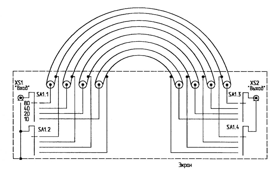
The screened box is closed with braided cable only in one place - either at the entrance or at the exit I will add. On the high-frequency ranges, if necessary, turn off the low-frequency repeater of the low-frequency range and connect the cable to the cable to reach resonance.
It is necessary to take into account that the line of transmission should be connected at the same time from the transitions of the additive windings, so that the internal soldering conduction may have its reactivity.
When working on the air, I have a vicarious simple, ale original uzgodzhuvalny attachment (small below). 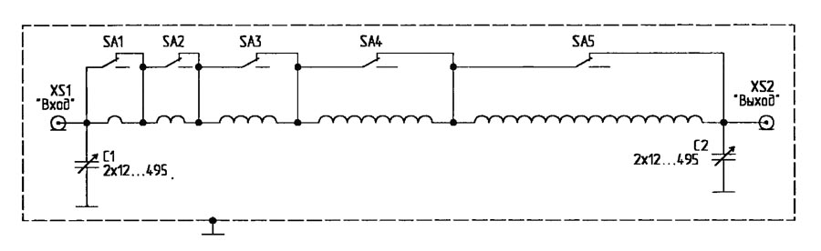
In fact, it’s a dodatkovy P-loop that needs to be changed. For the selection of the necessary inductance of the coil, vicorous toggle switches of the MTS-1 type are used, they are protected for a maximum stream of 6 A, so that the intensity of 250 W is superimposed, which is applied to the attachment. A way to include intelligence from a baby. The originality of the design lies in the fact that by combining the inclusion of toggle switches, you can take into account whether the number of turns and, if necessary, be necessary inductance. So, turning on the SA1 toggle switch (at the exit position
Normally closed contacts are wired), 1 turn is required, SA2 toggle switch - 2 turns, SA1 and SA2 toggle switches - 3 turns, SA3 toggle switch - 4 turns, SA3 and SA1 toggle switches - 5 turns. In this rank, it is easy to take the 31 position of the switch, which is important to reach with a rich position switch (I especially did not trim the switch more lower by 11 positions in the hands of the switch). In reality, this is another advantage of the “tumbler variometer”: the leather from the toggle switches does not lock the entire coil, but only a part of її turns. Obviously, the laces of this small tumbler will vibrate more tightness. І more: “turning” the mic allows you to take SWR = 1.0 on all bands.
The inductance coil is wound with a 01.5 mm dart with a 1.5 mm coil (two darts were wound on the cob) on a 06 cm frame and 31 turns.
Denmark's narrower attachment is extended right up to the 20-meter range (the coil has 1 turn), when working on lower, larger high-frequency bands, it increases the quality factor of the coil, made with the first turns. For example, vikonati first 3 - 5 turns from a tube with a 5-6 mm pereline. In case of difficulties with the sound of the tube, you can use a different way - wind qi 3 - 5 turns of the dekilkom with folded wires at once. So, for example, the length of the stake of a 6-mm tube (a high-frequency stream, as it seems, flows in a thin surface ball of the conductor) becomes 18.84 mm, and the length of the stake of 4 folds of 1.5-mm darts at once is also 18, 84 mm! A miraculous analogue of a flat tire comes out, as if it were necessary to poke around.
Capacitors of variable capacity - “primary”, 2 × 495 pF (type of tube radio receivers), therefore, it is necessary to win the SU when the supports are converted no more than 4 times lower. Uzgodzhuyuchiy pristriy nalashtovuetsya only once. At the cob stage, there is an improvement, although there is no difference in the superior work of the outward cascade with a possible high SWR, after applying a slight tension to the narrow attachment. Later, you will be able to get better if you have more tightness. I have seen the advance data of the coil: in the range of 20 m - 1 turn, in the range of 40 m - 3 turns, in the range of 80 m - 6 turns, in the range of 160 m - 10 turns, tobto. the first 4 tumblers are victorious. The rotor and condenser rotors in the changeable capacity are set to the middle position, and then they are adjusted to reach the SWR = 1.0. The numbers given are valid for 75 ohm input, and the stench will be adjusted for input, as may be the other opir.
Nadalі pіd hour of work at the air of victors, a table of positions by ranges has been compiled (if necessary, at some points of a specific range). After some “manipulation” with the narrow-width outbuilding, they are transformed at the reception desk.
I give the best respect to radioamators, as they have not previously victoriously adjusted the streak - ctbq, on those who, before it is necessary to install the handles for adjusting the tension, which are victorious in the position, visibly navantazhennyu with SWR equal to 1.0.
I'm going to use the vicorist this uzgodzhuvalny attachment to start it, if the input opir of the antenna becomes 75 ohms. Tsey uzgodzhuychiy pristriy actually є low-frequency filter and dodatkovo easing pozasmugovі vpromіnyuvannya transmission.
The experimentation of radioamators, like they work on the air, like antennas of the stench of vicorist showed that it is possible to install a high-width vicorist antenna of the Delta Loop type, or “trikutnik for 80 meters” according to ours. I got a little zatsіkavilo, the stars of such people's love to the antenna and virіshiv he prepared and tested it already from the zastosuvannya effective vimіryuvalnyh ZVL and Hewllett Packard devices. Between two crafty boudins, a tricot frame with a perimeter of 85 meters was placed. They tried to roztashuvati її so that the sides did not pass in parallel to the walls of the building. Zhivlennya was carried out at the kutku trikutnik. For the cob, the input opir of the antenna in the entire range was shrunk. Axis that we took away:
 |
As a matter of fact, from numerical values, the average support for all ranges is 240-300 Ohm. To this end, a balun was prepared with a transformation coefficient of 1:6. The actually prepared copy had a 1:5 transformation. On Smіta's diagram, the impedance at the output of the balun of the transformed support is 300 Ohm.

You can boulo b і pіdravity, ale virіshiv, scho tse not bad, shards of rozkid supports on the antenna itself and so great. After connecting the balun to the antenna, it is possible to predict the upcoming PCB schedule:
 |
 |
In this order, the SWR may be in the range:
- 80 meters -1.3-1.5
- 40 meters 1.4-1.7
- 20meters-1.2-1.3
- 17meters-1.9-2
- 15meters-1.9
- 12 meters-1.4-1.5
- 10meters-1,1-2
- on the entire range 28-28.7 MHz
Unfortunately, not all minimum SWRs are consumed clearly in the amateur range, but for such values, you can use the antenna to achieve the universal and highly efficient winds of the same size. Zrozumіlo, in the air, she won a good reputation for herself.
On the forums for molding viprominuvannya with vertical polarization, they mainly discuss the “delta” power supply to the “lower” (out of the earth) cut
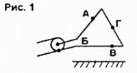
chi vіdstanі L/4 vіd "lower" points, tobto. near the earth.

On little ones 1 and 2, at points B and D, there is a strum bulge, at points A and C, there is a bulge of the tension.
Such a solution to the antenna, I immediately noticed: the antenna is installed low, and for such a power supply, the main improvement is near the ground. Before that, energize the antenna as shown in Fig. 2, next to the 9-surface - even if the placement of the cable is perpendicular to the antenna canvas, nothing is off, moreover, it’s good that the radio station was on the 9th version.
It seems that the greatest intensity of the electromagnetic vibration is located near the antinode of the strum: "the intensity of the vibration of the air in the air of the antenna is proportional to the square of the air to that air," tobto. the tension of the streak in the dermal duct of the antenna is the difference, the maximum is in the antinodity of the struma.
For the antenna, shown in Fig. 1, the antinode of the struma at point B is at the very bottom, and for the antenna in Fig. 2, it is three times higher than the lower part of the antenna, which is not so bad. Tim is not less, for a low-viscosity "delta" this option is not suitable.
Spiraling on the circle of the mirror, turning the antenna up from the power supply at the upper part on the L/4 line from the upper point (Fig. 3).

In fact, the antenna is “inverted”, shown in Figure 2.
In Fig. 3, it is clearly seen that the antinodes of the struma (points B and R) are raised to a greater height, therefore, the maximum
earth, which is even more important with a small height of the antenna. Before that, for such a configuration, it will be easier to move perpendicularly to the cable to the antenna canvas.
With a 10-meter height under the upper canvas, a dual-band (40 and 20 m) antenna was good, it was installed under the shoulder, because it is impossible to sprout її vertically for such a height. The lower point of the antenna is literally a meter from the ground, so it practically does not affect the effectiveness of the ventilation.
Here it is necessary to indicate that the expansion of the antinodes of the struma and the tension, shown in Fig. 1-3, are valid for the antenna in the range of 40 m. Horizontal.
The fabric of the antenna is made from a mid-range dart with a diameter of 2 mm in insulation. Delta є equal-sided tricot with sides 14.34 m, perimeter - 43.02 m. - 3.58 m. With such dimensions of the resonant frequencies of the antenna - 7040 and 14100 kHz, the antinodes of the struma B and G appear side by side.
With dotrimane proportions, for such direct antennas, the antenna can be more powerful. If necessary, manually shorten the lower kut, changing the height of 3.58 m, for example, up to 3.50 m.
I had a chance to see the balun at the point of supply, because won't give in to windy ambitions. Therefore, at the power supply point, an important balun was replaced on the cable by 5 ferrite shutters RF-130S. For good reason, I had a chance to look up and in case of any weather at the power supply unit. Shield cable connection to the upper part of the antenna, the central wire - to the bottom.
The most relevant characteristics of the antenna (the latest input opir and SWR) were taken by the analyzer AA-33OM for the help of a duplex repeater, prepared from a coaxial 50-ohm cable with a length of 14 m. Due to the insufficient height of the displacement, it is reactive to the warehouse input support, to that in the range of 7 MHz SWR = 3.0; in the range of 14 MHz - 4.0.
In such a situation, the solution to lower the SWR was praised by fixing the tight fitting of a 75-ohm cable. Combining the connection of short wires to such a cable with a length of 10 cm, 20 cm, 30 cm, 50 cm, 1 m, 2 m, 3 m, 3.5 m, provided with cheap TV roses, cable 9 m in the range of 14 MHz - 35 m, which allowed to take in the range of 7 MHz SWR = 12; in the range of 14 MHz - 1.5.
As a result, it was connected directly to the antenna with a 75-ohm windage cable 3.5 m, and even before the new one - a 50-ohm windage cable 8.6 m (total 14.1 m). Unfortunately, due to an inaccurate selection of the dvzhini of the napіvvilovogo repeater (the bula was marked with a rozrachunkovy way) in the range of 7 MHz, the SWR became 2.0; in the range of 14 MHz - 2.3. It's not so bad, with an SWR of up to 3.0, all the pressure goes into the antenna. Tim more, but less SWR movement in the cable start 14 m-code.
Cables are made with a diameter of 10 mm and a central conductor. Before the date of installation of cables, the binding of plastic cables with a length of about 15 cm, cutting with the diameter of the cables, which ensures the safety of the installation in case of wind winds.
Below, there is nothing to change the installation of the strum balun, with roses, which is still possible in phase with the strum.

In fact, SU at 7 MHz can be used in the ranges from 1.8 to 15 MHz. At 14 MHz, the SU has a coil with a mid-tube with a diameter of 6 mm (1 + 2 + 4 + 4 turns, a total of 11 turns), and can be twisted in the ranges of 7-29 MHz.
As a substitute for the remaining 4 turns of winding 8 (the last turns will be 15), then, in principle, the SU can be started from 3.5 MHz, and possibly, from 1.8 MHz (the next step is practical). Due to the simplicity of preparation, I have prepared 3 such SUs. As a result, after the narrow extensions, the frequency range without jet storage folded 400 kHz on the 40-meter band and 380 kHz on the 20-meter band.
This benefit was reduced to the lowest possible cost reduction on a 50-meter coaxial cable connected to another antenna switch. In two places, 20 ferrite plugs are installed on each cable. The SWR at the old cable connected to the exit of the uzgodzhuvalny outbuilding is close to one. Uzgodzhuvalni podstroi on zoseredzhenih elements can be replaced with additional plugs 75-ohm cable, if you happen to have any.
The antenna can be forgiven, as if it won't work on one band. In this option, the length of the 75-ohm winding cable, which is connected to the antenna canvas, becomes 3.5 m in the 14 MHz band and close to 7 m in the 7 MHz band. Uzgodzhuyuchy attachment can be installed in the adjacent radio station or do without it.
There is one more option: power the antenna only with a 75-ohm cable (for example, PK75-4-11). Itself so won in the minds of the sexes with a sing-song repeater (about 28 m) and a switch to 9 bands. Spring 2013 mi s Sergієm, RW9UTK, were tested in the field of minds from the equally rare RDA-region KE-21. The antenna worked on two bands and was installed at a height of 12 meters on two slate pipes. Pratsyuval antenna good - at other times we found out that such a pile-up.
There, near the field, the AA-ZZOM analyzer was used to simulate the characteristics of the antenna, as a result of the highest height, they appeared to be noticeably shorter, lower near the antenna, installed at a 10-meter height. At the range of 40m reactive warehouse buv zovsіm, Rin = 141 Ohm, SWR = 1.91, smuga beyond equal SWR = 2.0 - 80 kHz, beyond equal SWR = 3.0 - 300 kHz, active support is taken from smooth 800 (! ) kHz. In the range of 20 m, the reactive warehouse was also a day, Rin = 194 Ohm, SWR = 2.56, smuga beyond the equal SWR = 3 - 620 (!) kHz, active operation is taken in smooth 630 (!) kHz.
The service was carried out for the help of a self-contained control system, to which a 75-ohm cable was connected. Zastosuvannya uzgodzhuvalnogo pristroy allowed to gain on both ranges of SWR = 1.0 in a 50-ohm cable, which connects the SU with the transiver.
A wide range of operating frequencies without reactivity is the miracle power of closed antennas. There is no need to re-educate the SU in the boundaries of the amateur range; enough to master yoga in one point. With your SU, you can get far from the transceiver.
At the field, the canvas of the antennas was blocked by the field building of the P-274. This wire for polyethylene insulation can be shortened, so the perimeter of the antenna is even smaller, regardless of the height of the height, lower than the house, it becomes 42.70 m.
Here, too, the equal-sided tricoutnik with a side of 14.23 m. Between points A, B, C and D, the same equals are folded at 10.67 m.
There are some problems with the balun, which is to enter the warehouse of the universal line: for the re-supply of the antenna canvas, there were vikoristan plastic stakes in the shape of a pyramid toy, and the balun was trochic in the projected point (3.56 m at the top). After all, the antenna worked just miraculously, because. on 12-meter pipes, the bula is installed vertically.
It is planned to move the balun to the cob of the line, having provided it with roses. to save the protection of common-mode streams. In addition, on the cable, which lies on the grass, you can put on ferite "jumps" or pass a sprat once through the ferite ring - a cable with a diameter of 7 mm is allowed.
It is also planned to test the antenna in the floor of the mind, but even at a height of 16 m. The antenna will be mounted vertically. I will inform you about the results of testing.


