Self-contained GPS receiver for a car. How to build a PDA from a car navigator. Laptop as a GPS-navigator
I think for the greater part of you I won’t be convinced that the absolute majority of today’s car navigators work on the basis of Windows CE, but the operating system itself is dbaily attached to the vibrator from the hollow handles of the coristuvach, so that the wines don’t nakoїv zayvogo.
Let's just forgive it, but by a radical method - replacing the original Windows CE graphical shell with a shell like a builder I will add, as it starts when Windows starts. From one side, it’s good - a smarter menu, the main functions are launched in 1-2 clicks, nonsense in one word. Ale from the other side, the coristuvach of the surroundings is deprived of this functionality, which, having put a virobnik, the ability to install your programs is not transferred. However, it is even easier to establish the triumph of justice, if you only need a GPS-navigator, data cable, computer, which can be used with Win CE devices in Active Sync mode and some free time.
Respect! This instruction is not universal, but does help the best. Exploitation from scratch and creative experimentation can lead your navigator to an unproductive state, which can only be modified with a flashing. If you don’t think you need to work - don’t work, more nefig!
Otzhe, as if saying Gagarin: "Let's go!":
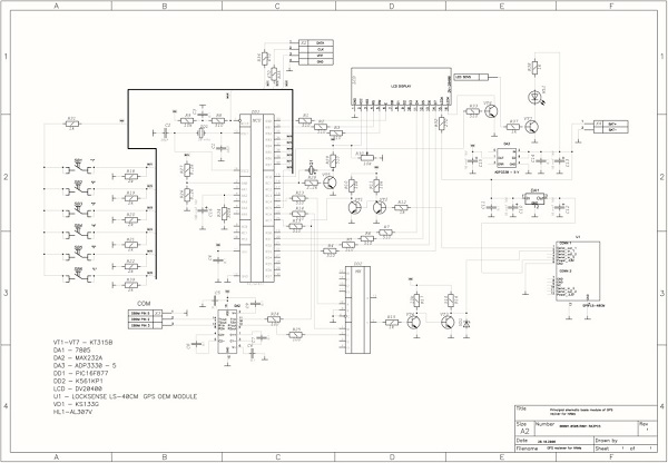
Even though I didn’t understand, then the axis of the picture de everything needed to be seen:

Don’t chip anything more than a smut, otherwise the chance to take away the stuffy stuff of the hall is even greater.
As a result, vykonannya tsikh simple diy vy z navigator take away a fully functional PDA on which you can easily install whatever programs you need. Dribnitsa is welcome.
Z.I. No way! Do you feel? No for any furnishing! Navite being drunk, stoned, stabbed (you need a seat), do not set a password on Windows. Navit with a method to marvel at what you see!
A fully functional PDA will not be able to teach you how to learn the basics of mirror photography, on the new one you can write down some instructions for amateur photographers, so that the stench will always be under your hand.
After a lot of experiments with Arduin, we worked out a simple and not too expensive GPS-tracker with the correction of coordinates via GPRS to the server.
Arduino Mega 2560 (Arduino Uno), SIM900 - GSM / GPRS module (for sending information to the server), GPS receiver SKM53 GPS.
Everything was purchased on ebay.com, the sum is about 1500 rubles (approximately 500 rubles for arduino, three less - GSM module, three more - GPS).
GPS receiver
It is necessary to get started with a GPS robot. Vibranium module - one of the found and simplest. Tim is no less, the speaker announced the presence of batteries to save data about satellites. According to the datasheet, a cold start is responsible for taking 36 seconds, but in my mind (10 on top of the subwindow, close to the booth no) it took as many as 20 whilins. Nastupny start, prote, already 2 hvilin.
An important parameter of attachments that are connected to the arduino is energy supply. If you want to change the arduino, you might burn out. For primach, the maximum power supply is 45mA @ 3.3v. Navischo in the specification to show the strength of the struma on the pressure, to the necessary input (5V), is a mystery to me. Tim is not smaller, 45 mA is changing the arduino vitrima.
Connection
GPS does not check, if possible RX pin. For what - nevidomo. The main thing you can do with this cipher is to read the NMEA protocol data from the TX pin. Rivnі - 5V, yakraz for arduino, speed - 9600 baud. I connect VIN for Arduino VCC, GND for GND, TX for RX of a valid serial. I read the data back to back by hand, then from the library of TinyGPS. Surprisingly, everything is readable. After switching to Uno, I happened to win SoftwareSerial, and then problems began - part of the symbolic support was used. It's not so critical, because TinyGPS has invalid notifications, but it's unacceptable to ask: you can forget about the frequency of 1Hz.There is little respect for SoftwareSerial: there are no hardware ports on the Uno (which is connected to USB Serial), so you have to win software. So from the wines, you can take the money only for pins, for which the payment is paid for the transfer. At the port of Uno tse 2 and 3. More than that, given one hour can take only one such port.
The axis looks like a test stand.

GSM receiver/transmitter

Now the cicavisha part is being repaired. GSM module - SIM900. Vіn supports GSM and GPRS. Neither EDGE nor more than 3G are supported. To transfer data about the coordinates, maybe, it’s good - there will be no jamming and problems when switching between modes, plus GPRS at once, it can be a little more. Prote, for some foldable additions, you can use it.
Connection
The module is also controlled by the last port, by itself - 5V. And here we need і RX, і TX. The module is shield, so it can be installed on the arduino. Moreover, sumisny like іz mega, so і з uno. Security fee for locking - 115200.We choose on Mega, and here the first unacceptable surprise is checked for us: TX pin of the module is used on the 7th pin of the mega. On the 7th pin, there is a mega inaccessible perevannya, which means that you will get the 7th pin, let’s say, from 6m, on which you can perevannya. In this rank, it’s worth one pin of the arduino marno. Well, it’s not scary for a mega-tse - still pіnіv vistachaє. And the axis for Uno is already more foldable (I guess, there are only 2 pins, which should be changed - 2 and 3). As a solution to the problem, you can suggest not to install the module on the arduino, but to replace it. Then you can quote Serial1.
When connected, we are prompted to “talk” to the module (do not forget to turn it on). We choose the port speed - 115200, for good reason, as all subsequent ports (4 on the mez, 1 on the uno) are used, and all the programs work on the same speed. So you can reach the stable transmission of data. Why - I don’t know, I want to guess.
Also, we write a primitive code for transferring data between the last ports, edited by atz and silence. What is it? Ah, as sensitive. ATZ is OK. Hooray, the module can sense us. Why don't you call us for the sake of interest? ATD +7499… Call my phone, the arduino is gone, the laptop is being destroyed. Zgorіv revamped Arduino. It was a bad idea to run yoga with 19 volts, even though it is written that you can use 6 to 20V, recommend 7-12V. In the dataset on the GSM module, nowhere is it said about the delay in the pressure on the advancement. Well, Mega is destroying the warehouse of spare parts. From the beginning of my heart, I turn on the laptop, having won + 19V on + 5V lines from USB. Pratsyuє and navit USB did not work. Dyakuyu Lenovo for zahist.

After turning around, I joked around the strum, what is going on. So the axis, peak - 2A, typical - 0.5A. So I didn’t give the power to change the arduino. Let's eat some food.
programming
The module provides a wide range of transmission possibilities. Starting with voice calls and SMS and ending, in the wake of GPRS. Moreover, for the rest, HTTP can be requested for additional AT commands. To bring the sprat to the right, but also to varto: you don’t really want to form the drink by hand. A couple of nuances about letting the data transmission channel over GPRS - remember the classic AT+CGDCONT=1, IP, apn? So from, here you need it yourself, but a little more cunning.To remove the page behind the first URL, you need to send the following commands:
AT+SAPBR=1,1 //Carrier carrier AT+SAPBR=3,1,"CONTYPE","GPRS" //connection type - GPRS AT+SAPBR=3,1,"APN","internet" //APN, for Megafon - internet AT+HTTPINIT //Initialize HTTP AT+HTTPPARA="CID",1 //Carrier ID for vikoristannya. AT+HTTPPARA="URL","http://www.example.com/GpsTracking/record.php?Lat=%ld&Lng=%ld" //Custom URL if sprintf with coordinates AT+HTTPACTION=0 //Request data using the GET method //get data AT+HTTPTERM //upinity HTTP
As a result, for the obviousness of the call, we take away the name of the server. So, in fact, we have already added data about the coordinates, as the server accepts them for GET.
life
Oskіlki GSM module like a converting Arduino, as I got it, a rotten idea, it was wrong to buy a converting 12v-> 5v, 3A, on the same ebay. However, the module does not need to be powered by 5V. Let's go to the hack: connect 5V to the pin, from which 5V comes from the arduino. Then, when the module's converter is installed (it is slightly more powerful for the arduino's converter, MIC 29302WU) to power those that the module needs from 5V.Server
The server, having written a primitive - taking coordinates and painting on Yandex.maps. It is possible to add various features, including the support of the rich coristuvachs, the status “on guard / not on guard”, the camp of the car systems (flying, headlights, etc.), it is possible to navit keruvannya by the car systems. Obviously, with a tracker support, which smoothly transforms into a full signalization.Polish testing
The axis looks like this when choosing a device, without a case:
After the installation of the re-energizing device, the system looks like this: 
Having soldered the darts, weaving a sprat of contacts from the arduino pads. Look like this: 
Having connected 12V in the car, having driven through Moscow, having finished the track: 
Krapki track to finish far one way one. The reason is that it takes a lot of time to collect data via GPRS, and during that hour the coordinates are not read. Tse is obvious pardon programming. Rejoice in a first way, by correcting a packet of coordinates by the hour, in a different way, by an asynchronous robot with a GPRS module.
An hour of searching for companions on the passenger seat of a car - a couple of hvilins.
Visnovki
Do-it-yourself creation of a GPS tracker on Arduino is possible, even if it is not for trivial tasks. Smutty nutrition at the same time - how to hide the attachments of the car so that the wines did not fall into the influx of heavy factors (water, temperature), were not closed with metal (GPS and GPRS are screened) and were not especially memorable. For now, just lie in the salon and connect to the smoker's nest.Well, you still need to fix the code for the smooth track, if you want the main task of the tracker and that's it.
Vikoristani annexes
- Arduino Mega 2560
- Arduino Uno
- GPS SkyLab SKM53
- SIM900 GSM/GPRS Shield
- DC-DC 12v->5v 3A converter
Specialized stores have a wide range of GPS attachments in different price categories. Harder models with expanded functionality are expensive to complete, and the simplest beacons are aired at an affordable price. Tim is no less, there are many who try to get lost and prepare a GPS tracker with their own hands. How much folding is needed, what do you need for її vyshennya and what do you really need to stained zusilla?
Smartphone wiki for GPS tracker
To win a smartphone with GPS function, like a GPS tracker or a beacon, you need to fix a little bit of software security. Building a GPS tracker with your own hands on a phone based on Android, Windows Mobile or iOS is even simpler, you don’t need any kind of construction. Like a smartphone will zastosovuvatisya like a car tracker, you will be able to perform clumsy manipulations about connecting to the electrical system of the vehicle.
Use a small program that allows you to turn your smartphone into a tracker. To install on the Android platform, you can download the Loki program on Google Play, run yoga on your smartphone and install it. It is recommended to activate the following functions:
- autorun;
- povіdomlennya (for bazhannyam);
- zvnіshnє zhivlennya (vykoristannya alternative nalashtuvannі when connected to zvnіshny dzherel zhivlennya);
- outside awakening (behind the bazhannyam);
- command wrapping.
For navigation (definition of exchange), it is recommended to set the data update interval once per quarter; Nalashtuvannya at the distribution “Podії” zdіysnyuvati vіdpovіdno to the needs of the authorities.
Once you have completed your registration, you will no longer need to register on the Asgard website and add your attachments, indicating the identifier, and assigning them to the Loki program. As a result, the sign of your distribution area appeared on the map of the site, which means that everything is set up correctly, and the smartphone can be labeled as a tracker, showing it through Asgard.
Also for Android you can tweak the GPShome Tracker program, and for Windows Mobile - GpsGate Client for Pocket PC. When converting a smartphone to a tracker or a beacon, it is important to set the time zone correctly.
For assigning coordinates through Wi-Fi and GSM networks, the mother is responsible for access to unlimited mobile Internet, so you need to choose a tariff that allows you to optimize your network. If the phone of the victorist is to be turned on as a tracker, it is better to insert a SIM card only for accessing the Internet, and not for calls. Using a GPS-receiver, which promotes the accuracy of the coordinates, is a very energy-consuming process, so the next concern is about the safety of the life of a self-contained tracker. For which you need to trim the lower end of the auto plug (cigarette plug) and insert the charger cord into the phone at the USB sockets. To connect the tracker directly to the on-board system, it is necessary to add a lower converter of the power stream. And those who know little about electronics can choose an analogue of a converter with a pair of capacitors and a stabilizer.
As a self-contained tracker (beacon) it is planned to win for the fastened fastness behind the movement of the car, it is necessary to think over how to do it so that at the time of consumption it can be easily reached. І do not forget to activate the silent mode, as the phone has a card for the Internet and calls.
How to make a do-it-yourself GPS tracker with a great phone
The simplest model of a mobile phone without GPS can be turned into a lighthouse, but for which you need additional possession and report more knowledge. Required materials and tools:
- mobile phone;
- GPS/GPRS module;
- GPS receiver;
- adapter (you can change the old charger attachment with a working plug);
- lower and soldering iron.
Having cut off the charging attachment from the side of the life block, it is necessary to clean the darts and solder them to the module board, and insert the plug into the life socket of the phone. Potim vmikaєtsya priymach and nalashtovuєtsya phone. For the help of such an outbuilding, you can provide the space for mobile phones, as if you belong to your homeland. Information about their coordinates is sent to the mobile phone connected to the GPS-module, in front of the most prominent text messages.
Deyakі operator merezhi proponuyut service "Beacon", activating її possible on any mobile phone without a GPS-module. A list of contacts of subscribers is being compiled, the list of such contacts is required. To take care of the coordinates, you need to send a request to the inserted form.
Can you use a GPS tracker without a phone
An alternative to using a smartphone or a telephone in a complex with a GPS module is any attachment with a GPS function (laptop, PDA). The principle is the same, like for a smartphone - the installation of the program, the installation, the registration will be added to the site.
And how can you pick up the GPS-module and receiver with your own hands, how do you build a beacon or a tracker? The axis of the deakі components that enter the warehouse tsikh outbuildings:
- photoresistor, sound short;
- operational support for the improvement of bipolar transistors;
- vipryamlyach;
- capacitor type controller;
- filter parts;
- impulse trigger.
You can buy all these details, and I’ll build a scheme - you can know it on the Internet, but not everyone can learn how to build a GPS tracker with your own hands.
Advantages and shortcomings of a self-contained design
As an old and non-traditional phone (smartphone), the main advantage of converting into a tracker is economy. How to get a device specifically for your needs, the savings in preparing a GPS tracker with your own hands is practically imperceptible. The design of a mobile phone and a GPS module can be cumbersome, people carry it around handlessly, and when installed in a car, a great risk of shaving the wires. A smartphone is like a tracker, or a beacon of vikoristovuvaty more conveniently, but only for following people. Installing on a car is not the best solution, the original tracker may have a low advantage over self-confidence:
- until the time of the pratsyuє vіd batteries;
- without any tricks, they are connected to the onboard railing, saving a minimum of energy;
- applications for operation in a wide temperature range, lower telephone;
- zavdyaki airtight body can be installed zvnі avtomobilya;
- react to blows, rozgoduvannya auto;
- can be equipped with an alarm button, a microphone, various sensors.
Just like cheating a smartphone as a hooked-on rig, the function of a communicator is not possible to cheat.
It is better to buy a GPS tracker or a beacon, lower your self-confidence attachment on the basis of a smartphone or a great mobile phone. The factory tracker is the best, best installed on the transport zasib, having more functions. The cost of buying a tracker is not so great, and the conversion of a smartphone to a fast pace is true only for the obviousness of an obscene device.
Regardless of those who are currently on the market, you can find an impersonal GPS device in a different price category and functionality, not everyone is ready to buy a ready-made navigation device and free to do it with their own hands. Chi needs to be said smoothly, ale, without a doubt, it is possible.
Vlasny navigator can be used in two different ways. For the first one, you need the simplest mobile device, a GPS transmitter and a battery. In front of the warto, there is no sense to report on it, for folding a self-contained navigator in such a way requires a lot of trouble and an hour, and more importantly, it is necessary to sort out the electronics and the basics of system programming well - so not all of them. Before that, such a foldable navigator has a victorian, asking for a companion to inform you, we take the coordinates from you, so that you can put them on the map.
Another simple and effective way to skin is a GPS navigator, using a laptop for assistance. What do you need for whom? In a first way, the laptop itself, in a different way, a GPS receiver, for example, is used by a current mobile phone.
GPS-receiver is connected for any kind of interface (Wi-Fi, Bluetooth or USB) from a portable PC. The rest of the year is practical for the skin, until then, for the navigator, it will be enough to navigate the simplest netbook or tablet.
Before connecting the GPS module, it is necessary to take care of it, so that on the PC there was a separate program security, so that you can install it. To know and take advantage of yoga from the Internet is not a warehouse of any difficulties, so the choice here is incredibly great. Deyakі programs pіdіdut for foreign trips at long distances, deyakі, navpaki, for trips by city. Since a PC can access the Internet, you can also install programs to give information about traffic jams.
Having connected the navigator to the PC, it is necessary to check in, while it is possible to designate the system, as well as it is necessary to add additional drivers, it is necessary to install them. It is not necessary to do a search, you can simply install an automatic search on the Internet. Attached - you can run the navigation program and change it, you can see the attachment. If everything is ready, a self-contained GPS navigator is ready, if you blame problems, you need to dig around in the patched software.
Chi varto build a navigator with your own hands, or better than buy it - virishuvati skin on the ruling court. Whether it be for a vipad, in the first, or in another vipad, you will have a chance to report zusil and spend an hour.
The receiver sees the following data:
- Coordinates - latitude, longitude and altitude of the point, in which to know
- Hour after GMT - years, hvilini, seconds
- A large number of companions, revealed by their primacy
- The number of satellites from which the signal is received.
Primach can remember 200 pixels. The memory can also store the coordinates of the points that are indicated by the receiver at a given moment of the hour, and the ability to record the coordinates of the points from geographic maps in the memory of the receiver is also added.
For an additional primach, you can determine that true (do not confuse with magnetic) azimuth from the point in which the primach is located, to whatever point, chosen from memory.
The EB-500 module is wonderfully suitable for mobile applications, the shards may be small in size and small in size.
Accuracy of coordinates to be deposited depending on the number of satellites, the signal from which can reach the module, they can be no less than 3.
For satellite display, the vicorist module has 66 channels, with which, as a passive antenna, it uses 28 mA. After the appearance of satellites in the number of channels and, later, the strum, which settles down, changes.
The voltage of life is 3 to 4.2 volts.
The call from the module is for two equal UARTs.
UART pins - TX0, RX0 and TX1, RX1.
On the output of the GPS status connections through the resistor light diode. As long as the signals from the satellites are not installed, the logical 1-light diode burns steadily, when the satellites are detected, it flashes with a frequency of 1 Hz. After the adjustment of the yoga scheme, you can take it.
Visnovok V_RTC_3V3 – for this vysnovok you need to pay a living, without which the module will not start. You can power up the module, or rather, connect a standard 3-volt CR type lithium battery, then all settings will be saved in the module's memory and after switching off. The RTC slowdown is less than 1 µA, so the batteries need to be pulled out for a long time.
Life is submitted for viewing VIN_3V3.
The antenna is connected until RF_INPUT is displayed. The track that connects the module with the antenna feeder can be a short one from the earthen polygon from the sides. I have a passive antenna
35*35 from polygon under it 70*70. It started up without any problems at the fog on the forest galyavin. And the accuracy is more than decent.
A good active antenna is expensive, a good LNA is not cheap. A cheap Chinese antenna, in the minds of strong overshifts, showed itself to be more passive, as you can see there, the subsiluvach is not very low noise. In addition, it will live at a minimum of 3.3 volts, and from the module it will be fed into the line.
2.8 V. That requires a constant voltage output by the capacitor to output RF_INPUT, open the antenna, start the sound of life - a lot of trouble.
The antenna should not be placed instructed by the module, so that the noise from the module was not disturbed.
Tse on the GOOGLE map plotted the coordinates of the virtual point. Vіdstan vіd stіni budinku vіd vіd vіd 10 mіv.

In addition, as the module will be soldered on the board, VIN_3V3 and V_RTC_3V3 are connected, the antenna is switched on according to the light of the light, so everything is working for you - you need to check the speedexchange UART. Necessary for programming the USAR (synchronously asynchronous receiver) of the microcontroller.
Connect RX1, TX1 or RX0, TX0 via MAX3232 (applies to 3 volts) s COM port of the computer. For USB, you can solder the transition to the FT232RL - an inexpensive, superior microcircuit with drivers for all operating systems. I ordered one with no problems.
Change the speed, on which module it looks like, according to the datasheet 9600 I have earned 115200. The signal for which is not obov'azkovym - the light may not shine. I use the terminal at CVAVR, or I use the Terminal v1.9b program, which is free of charge, and it’s already handy.
The exchange is based on the NMEA 0183 protocol.


ATMEGA 16 binding is standard. Visnovok REZET is pulled up to life with a 10 kOhm resistor. The clock frequency is determined by a quartz resonator 7.3728 MHz. Live power to the ADC of the microcontroller is fed through an LC filter - a 10 μH inductor, a 1 μF capacitor. ADC reference voltage monitoring AREF is disabled for ADC voltage monitoring. Roz'em for the programmer on the scheme is not evidence. To port B connections LCD display WH1604B - 4 rows of 16 characters. Substroyuvalnym resistor R2 20 kOhm adjusts the contrast. Button for switching the clock to save battery charge.
Between the UART module and the USART of the microcontroller, an ADUM1201 microcircuit is installed as a galvanic decoupler. The maximum amplitude of the pulses per module, as seen by the oscilloscope, is not more than 2.8 V. The microcontroller receives a pulse as a single pulse per 2.5 V. To get rid of ADUM troubles, put it more quickly.
AT24C128 chip is electrically erased and programmed permanent memory (EEPROM) with I2C bus interface - receiver memory, deletion of all 200 points data, but about the last one. The CDL-synchronization of the serial link and the CDA-serial data transmission and the addresses of the fault are pulled up to live by a 4.7-5.1 kOhm resistor. Visnovok WP-zahist vіd record z'єdnany z GND. Visnovki A0,A1-driver addressing are switched, as if a small number of microcircuits are connected to the bus, 4 combinations are possible. We have one microcircuit, to which A0, A1 are tied to GND - addresses are up to zero.
A doctor was selected for the operating room. The battery voltage is measured and applied to the ADC input of the microcontroller - bit port A, to control the voltage value of the lithium battery.
The keyboard for spilkuvannya іz priymachem zіbrana on tact buttons. The READ and WRITE buttons are clocks. Hover button - with fixation. Resistors 300 Ohm are needed for the exchange of the struma, so as not to burn the port of the microcontroller.
Now about eating priymacha. I have a 3.7 volt lithium battery, with a fresh charge of approximately 4.15 volts. To run the microcontroller with quartz 7.3728 MHz and the WH1604 display, 5 volts are required. If you want to display Vdd 3 to 5 volts in the dataset, but with a standard scheme for adjusting the contrast ratio and voltage of 3.3 volts, nothing is visible.
Apply 3.3 volts to the EB-500 module. On the LM2623 microcircuit, a pulse stabilizer is selected, which moves it to 5 volts. The LM2623 microcircuit is designed specifically for digital equipment, it has a low noise level and a minimum of binding. Capacitors C4 and C5 are installed additionally for noise reduction.
Life for the EB-500 module is taken from the output of the LP2980-3.3 line stabilizer. A microcircuit with a rather low voltage, spend a maximum of 50 mW on it, it heats up a little, and it is necessary to stabilize 3.3 volts with practically no noise.

Now about the program. Vikoristany compiler.
Protocol NMEA 0183 to revenge richly be-like korisnoї іnformatsії, but we can only chirp coordinates, hour, altitude above the sea level, the number of visible and victorious satellites. To that, we choose only 3 reminders (necessary information is seen with a chervonim):
1.$GPRMC,181057.000,A ,5542.2389,N,03741.6063,E,0.47,74.50,190311,A*51
Here we have to click on the character number 18 (it starts from 0) if A is the data valid (є signal), if V is not valid.
2.$GPGGA,181058 .000,5542.2389 ,N,03741.6063 ,E,1,8 ,1.34,115.0 ,M,14.6,M,*54
Please take all the information.
181058.000 - hour
5542.2389 ,N - latitude
03741.6063 ,E - longevity
1 - GPS fix (0 = Data not correct, 1 = Position fixed, 2 = DGPS (adjusted accuracy))
8 - number of vicorist satellites
1.34 - HDOP, horizontal accuracy
115.0 ,M - height above sea level
14.6,M - Geographical visibility - difference between the terrestrial ellipsoid WGS-84 and the sea level (geoid)
The hour after the last DGPS update is daily.
3.$GPGSV,4,1, 13 ,28,65,075,17,26,53,202,37,15,50,278,17,27,39,290,24*7D
Here we are symbolized by numbers 11 and 12.
13 - Povna number of visible satellites.
As soon as the receiver is turned on, the ADC is started (by setting a single 6 bit to the ADCSRA register of the ADC of the microcontroller) to check the level of the lithium battery charge. After the ADC conversion is completed, 100 values are taken from the data register, then the average value of the battery voltage is calculated. If the voltage on the battery is lower or more than 3.2 volts, a message “ Discharge accumulator". The limiting voltage, to which the 2.7 volt battery can be discharged. It is better to bathe the battery with a charge controller.
USART register of the microcontroller UCSRB=0x90 does not mean that it is allowed to restart after the completion of the acceptance and inclusion of the acceptance. The function of processing the transfer after the completion of the reception is in the offensive:
Data is taken from the UDR buffer register for the reason that (UCSRA&=0x18)==0, so there is no framing pardon flag and a redeployment flag in the UCSRA register. Whenever the receive is rebuyed from the read/write mode (changed flag=1), the data is simply taken from the USART receive buffer, but the buffer was reflowed. Try to turn on the USART receiver for an hour before communicating with the module. If flag=0, the data taken from the buffer is parsed. Once the head of the row is found - the $ symbol after the ASCII code 36, the entire row to the end - code 13 (carriage rotation) is sent to the gps array. Then we change the symbols from gps, gps and gps, we can tell you RMC, GGA or GSV all other information will be ignored. Just a reminder of RMC, change a equate to an element to the gps array, like GSV - it is calculated from the symbols that are in gps and gps the number of visible satellites. As a matter of fact, the GGA is transferred from the functions of the transfer to the main program. At the program, the mailbox is checked a 86 the symbol V behind the ASCII code is the signal’s presence, the display will show the message “ No signal”

How to change a = 65 - the symbol A does not mean that a signal has appeared. Let's move to the gps array, where all the GGA information is placed, all the data that we need to call. Calculate the hour, coordinates, the number of satellites from which the links are set, the height above the sea level. All this data plus the number of visible satellites calculated by the reset subprogram is placed in the buffer for viewing on the LCD and displayed on the display screen. This picture comes out:

At the first row, the latitude of the point and the number of companions are displayed, with which a link is inserted, their sim. The other row is the length of time and the number of visible satellites is 11. The third row is the hour after UTC and the height above the sea and the ocean.
To record data, press the "Record" button. All data is stored in the external EEPROM AT24C128 EEPROM chip memory with I2C bus interface. The memory of the microcircuit is organized as 16,384 lines of 8 bits for the skin. Internal 16384 bytes of memory divided into 256 sides of 64 bytes per skin. The record can be viewed both byte by byte and by the sides. For the forgiveness of life, a post-record entry was selected. Microchip addresses one byte: the three most significant bits of the AT24C address are set to 101, the remaining bit indicates writing or reading. Like zero is a record, one is a read. Memory addressing - two bytes, the older bit is the number of the young side - the number of the word on the second side. Output: side numbers from 0 to 255 - 8 bits plus line numbers from side 0 to 63 - 6 more bits, so 14 bits are required for memory addressing. To remove the high byte, take the number of the side and break it to the right in two positions - two high bits are reset, and six high bits of the address of the side are moved to the six young ones. Let's change the same side number to the left by six positions and take the youngest byte of the address, de two older bits - two younger bits of the address of the side, the other six - zero. Now you need to remember the address number of the calling memory for the point to be recorded. For which vicorist, the non-volatile memory of the microcontroller is EEPROM. For ATMEGA16 EEPROM store 512 bytes. There are two arrays in EEPROM: eeprom unsigned char ad and eeprom unsigned char opred. The ad array points to the free side of the memory АТ24С128, one means that the side is occupied, zero means free. For example: ad=0 means that side 20 of memory AT24С128 is valid, and that ad=1 is also occupied. Before that, in order to write data to the outer memory, we iterate over all the elements of the ad array, incrementing the element number g like 0, until the intelligence ad[g]=0 is found. Addresses of the side of the old memory g. Now remember the address of the side of the memory AT24C128 to the number of the point to be remembered. opred[point number]=g (address of memory side АТ24С128). If you need to erase the data of a point, then zero is written to ad[the number of the point to be erased], and the numbers of the elements are moved to the opred array, so that, starting from the number of the point, one more is erased: opred[the number of the point] = opred[the number of the point- 1], And the number of the total number of recorded points is changed to one. If it is necessary to erase all data from memory, the number of recorded points and array ad is reset to zero. When writing new data to the riddle about AT24C128, the old data is erased. Changing the number that indicates the total number of recorded points is also located in the EEPROM of the microcontroller.
The record looks like this:
It is pressed for 50 ms (a delay of 50 ms is installed on all buttons) the “REC” button. On the display screen in the first row you will see: “ Tpoints: (no. points)” point number recorded in the EEPROM of the microcontroller at whom increminate. If the point number is moved to 200, it is indicated Memory busy” This receiver exits the recording mode. In another row, you need to enter from the keyboard the name of the point up to 16 characters from the numbers and small letters of the Russian alphabet. The principle of introduction is the same, like that of a mobile phone: click on the keyboard button, the required symbol will not appear. When miltsi set, the symbol is erased with gratas. The keys of the keyboard are connected to bits 3,4, 5 to port D and to bits 2,3,4,5 to port C. To port D is fixed as an exit, to port C as an input with a lift. On bit port D with a frequency of 5 ms, a low level is applied, and when the value of the bit in port C is read. 3 dezhzh. The button is active for 2.2 seconds - 16-bit timer T1 starts at a frequency of 28800 Hz when zero appears on the input bit port C. When the timer passes the value 65535, a retry is generated and the program switches to the retry processing function. If another button becomes active before the end of 2.2 seconds, then, as soon as the timer is reset, the timer will start, and all values entered before the active button will be reset. After the set, name the points - it’s pressing *. The third row shows a reminder " Flow point?” It is necessary to remember the point, which is indicated by the time we press at a given moment *, a reminder will be shown on the display “ Krapka recorded” This receiver exits the recording mode. When you enter the coordinates from the map, press #, the screen will display the “ Latitude?” Enter the latitude coordinates of all digits without dots - 49˚52 "16.54" enter, like 49521654 then we press *, the power will be displayed “ Dovgota?” so enter it yourself and dovgot, deputy 3618 "51.57" - 36185157 and then *.

The display shows the message “Krapka recorded” This receiver exits the recording mode. When writing coordinates from the map, the height value is not recorded and the coordinates of the height point are zero when reading the coordinates. The entry for the EEPROM AT24C128 is sequentially read as follows:
- A smart start is being formed - moving from a high to a low camp on the SDA for a high SCL.
- Bytes are transmitted from the address of the microcircuit 10100000 the remaining bit is 0 - write.
- The first byte of the memory address is transmitted, then the other byte of the memory address.
- Bytes of data are transmitted, the addresses are written on the side when they are credited. Change the SDA output if the SCL output is low.
- Mind grains are being formed - the transition from a low level to a high camp to the SDA for a high level of SCL.
To read data from the memory, you need to press the "Read" button (with 7 bits of port C, a logical zero is read) and the display will show: " Krapka:". Dial the number of the coordinate point you want to read, and emboss *. The coordinates of our point are displayed on the screen. When entering the point number in the reading mode, only a number is available on the keyboard. Whenever a number is entered, the number of which I change the number of recorded points, a reminder will be displayed “ No data”, then we turn around: “ Krapka:". As there is no saving data in memory, when you press the “Read” button, a reminder will appear “ No data” that attachment exits the reading mode. It is read from EEPROM AT24C128 as follows: start, stop, understand that addressing the same way, as when writing. Addresses, for which point coordinates are recorded, which are read (for the program, the number of the point of change of values \u200b\u200bnomer_1) is known in the opred EEPROM array of the microcontroller. High address byte will be opred>>2, low opred<<6. Только после передачи второго байта с адресом памяти посылается байт с адресом микросхемы 10100001, где последний бит 1 – чтение. В программе чтение идет побайтно, сначала считываются байты с названием точки. Считывается байт, по номеру кода в считанном байте определяется строка, содержащая код знакогенератора LCD модуля и символ соответствующий этому коду выводится на экран, затем младший байт адреса памяти инкременируется. Так выводятся 16 символов названия точки. Затем считываются байты с данными широты, долготы и высоты точки. После считывания очередного байта младший байт адреса памяти инкременируется. Все считанные параметры помещаются в буферы для вывода на LCD и выводятся на экран дисплея:

You can re-gorge the data after the increasing numbers with the number 2 on the keyboard, after the falling zero. Exit from read mode #. In reading mode, data can be erased one point at a time or all at once. A dot is displayed on the screen, data that needs to be erased and pressed *. Examples of the first row are “Store?” For confirmation *, but not - #. If it is necessary to erase all data, then it is successively pressing *, it appears “Store?” , embossed on 1, zamіst“Store?”z'is” Mustache?” as confirmation - *, ні - embossed on #. When erasing into the EEPROM array of the microcontroller - ad, which indicates the correct address of the side in the memory of AT24C128, zero is written to the element, with the number equal to the address of the side in AT24C128 of the point to be erased. Data from the side is erased at the hour of writing other data in it, so it is not possible to turn on the acceptance of the recording mode, the docks will not show up “Krapka recorded”.
The receiver has been switched to the aiming mode. In this mode, the true azimuth to the point is displayed, in which the receiver is known to any point, chosen from the memory of the receiver. To transfer the receiver to the guidance mode, press the "Guidance" button, with another bit port D reads a logical zero. On the screen, the request “ Krapka:” it is necessary to enter the number of the point and the azimuth, to which it will be calculated, then press *. The coordinates of this point are placed in the array of kr locations in the EEPROM of the microcontroller. The number and name of the point will be shown on the display screen, then the message “ guidance This display screen looks like:

An azimuth (287˚1 "48") is displayed on the cob of the fourth row, after it go to the point that we should be called (3284 meters). So you can walk in azimuth, for example, a compass є. Magnetic observation - the difference between magnetic and right azimuths is indicated on rich maps. Formulas for calculating the azimuth and the distance taken from a handyman from a geodesy and converted for a robotic change of the float type. The pointing point coordinates are stored in the non-volatile memory of the microcontroller, so if you deactivate the “Aiming” button and turn off the attachment, then after turning on the attachment, continue aiming at that very point. To change the aiming point, you need to press the button, reach the signal and dial the number of the new point.
The design will fit, obviously, it will fill up the best things, but what happened, those things happened.
What is needed f'yuziv, I have programmed only BODEN - the switching circuit is enabled when the voltage is reduced, and SUT1 - controls the mode of starting the clock generator when the switching circuit is turned on. Others are not programmed, so they are equal alone.
List of radio elements
| Appointment | Type of | Denomination | Kіlkіst | Note | Score | My notepad | |
|---|---|---|---|---|---|---|---|
| Scheme 1. | |||||||
| U1 | IC RS-232 interface | MAX3232 | 1 | Do notepad | |||
| EB1 | GPS module | EB-500 | 1 | Do notepad | |||
| D1 | Svitlodiod | 1 | Do notepad | ||||
| C1-C5, C12 | Capacitor | 0.1uF | 6 | Do notepad | |||
| C8 | Capacitor | 100 pF | 1 | Do notepad | |||
| C9, C10 | Capacitor | 4.7uF | 2 | Do notepad | |||
| C11 | Capacitor | 0.01uF | 1 | Do notepad | |||
| R7 | Resistor | 1 | Do notepad | ||||
| J1 | Roz'em | RS-232 | 1 | Do notepad | |||
| Antenna1 | Antenna rose | 1 | Do notepad | ||||
| L1 | Inductance coil | 1 | Do notepad | ||||
| IN 1 | Life Battery | 3 V | 1 | Do notepad | |||
| Scheme 2. | |||||||
| U2 | microcontroller | 1 | Do notepad | ||||
| AD1 | microcircuit | ADUM1201 | 1 | Do notepad | |||
| OS1 | Operational helper | 1 | Do notepad | ||||
| AT1 | microcircuit | AT24C128 | 1 | Do notepad | |||
| C6, C7 | Capacitor | 0.15uF | 2 | Do notepad | |||
| C13, C17 | Capacitor | 0.1uF | 2 | Do notepad | |||
| C14, C16 | Capacitor | 22 pF | 2 | Do notepad | |||
| C15 | Capacitor | 1 uF | 1 | Do notepad | |||
| R1, R3 | Resistor | 20 room | 2 | Do notepad | |||
| R2 | Substroyuvalny resistor | 20 room | 1 | Do notepad | |||
| R4 | Resistor | 10 ohm | 1 | Do notepad | |||
| R5, R6 | Resistor | 4.7 room | 2 | Do notepad | |||
| R8 | Resistor | 10 room | 1 | Do notepad | |||
| Y1 | quartz resonator | 7.3728MHz | 1 | Do notepad | |||
| L2 | Inductance coil | 10 µH | 1 | Do notepad | |||
| DS1 | LCD display | WH1604B | 1 | Do notepad | |||
| K1 | Tact button | 1 | |||||


