Z match is a convenient attachment for a symmetrical antenna. We will be "Z-match" antenna tuner. Antenna tuner design RZ3GI.
Descriptions of the tuner assignments for the use of a non-symmetrical transceiver output with a symmetrical live line.
For molding of a symmetrical stagnation signal, the original vuzol, vikonaniya on "binoculars", prepared from ferite tubes with great penetration into the monitor cable. Vikonan changeable inductance coil on Amidon T200-2 coil and may inductance 40 μH, breakage leads step by step to the end. Usyi Visnovkiv -15.
Sequentially from the main (up to the cob) is included a coil with a few turns of 1.3 mm thick thread wound on a mandrel with a diameter of 10 mm and slightly stretched (practiced on HF). Up to KPE 12 * 520 capacitors of constant capacity are connected, which add up to 1000 and 1500 pF. (Actually, up to 1000 pF is enough)
The back wall of the body of the vikonan is orgskla. All parts of the tuner have no electrical contact with the case.
The coils in the "binoculars" are braided (a coil of a tie) and the inner core of the fluoroplastic cable (crossed). Double-core cores (30VCh and 100HN) did not work well. As a KPE, it is possible to put two (chotiryokh) sectional KPEs in the form of lamp fixtures, at its own housing, KPEs can be connected from the “ground”, tobto. the body of the input rose, and the stators are connected to the binoculars. With an intensity of up to 100 W, such a KPI is not flashed.
If the symmetry of the signal is broken (through installation), it is possible to connect between one of the outer terminals and the "earth" a built-in capacitor up to 30 pF and connect an oscilloscope or an RF voltmeter to "read" the signal. On the cable that goes into the transiver, it is necessary to install a ferite clasp for the tuner's rose.
On inputs up to 600 ohms, the SWR does not change 1.1.
The tuner is matched with the G 5RV antenna and FT-817, FT-857 transceivers.
Changing the inductance can be changed to any available viconnance with inductance up to 34 μH (significantly less on band antennas). "Binoculars" can also be worn on other tubes, straps or rings, including the vodka virobnitsa, shoes and tongues, with a minimum penetration rate. In this case, before installation in the tuner, it is necessary to carry out a re-test for the daily heating of the ferrite on the working pressure. For QRP, the tuner can fit literally at the cigar pack.
When prepared by the tuner, we collected materials from the installation of "binoculars" from Valentina. RZ 3DK that Igora RZ 3DOH.


Tse still only sketches of statistics ... I'm working on ... Trochs about manual tuners.
Obviously, it is important that the most effective antenna is the same range and resonant. Іz cym none are interfering. But don’t start the mother’s ability to dial such antennas, but one is universal. And for going out into nature, if there is no other meaning, then the placement of antennas is not transferable, the presence of a light, small-sized antenna tuner becomes even more important. Obviously, you can vicariate the latest from me LDG Z100, which is a whole lot of work for a couple FT-817ND. Ale, still sho tse zayve. Let's think about a remotely ceramic tuner for an antenna, and after reading various articles, some of them are given at the bottom of the article, for revisions and preparatory work, we have to work "for testing"
small tame Z-MATCH tuner.
Why vibir falling on itself Z-MATCH?
Basically, through those who can win one pen less! This is important, for those who want to get a remote tuner in the future.
The "reserves" had a pair of small-sized replacement capacitors for intestinal radio receivers. One of them is doubled, on the new one it is written 4-240 pf. , Ale really change 25 pf. - 250 pf., i single, it is written 10-450 pf. - 460 pf. (Below 25 pf. on the edge of the attachment). Obviously, such capacitors cannot be used because of the great tension, but FT-817ND go all the way.
In reality, there was a spear of a ring with a size of 20x12x6 mm, but there was no magnetic penetration. It was suggested that it was 50 PN kіltsya, but it also required a recheck.
For the determination of the magnetic penetration of the ring, the UA1ZH program was used. On the kіltse, shokaetsya, winding a sprat of turns (in my opinion, for goodness 10 turns), with an attachment AA-330 the inductance is selected, then the program is presented with the number of coils, the number of turns and the inductance, and the value of the magnetic penetration is displayed.

This procedure confirmed my guess about the magnetic penetration of the ring at 50 Mon.
Tim an hour, buv pіdіbrany pokhіdny corps, roz'єmi zatiskakhі, small-sized switches, svіtlodiod for the indicator.


Tim is a tuner for hours. (Photos will be a little later). However, the follow-up of the tuner for the help of the AA-330 antenna analyzer brought the deacon a rejoicing, as it led to understanding ...
To get to the tuner, a 50 ohm test drive was connected. As a result, it was far from being possible on all amateur bands... Well, at 160 m I did not succeed: -) - there is clearly a lack of inductance. Ale unpracticedatnіst on 10 and 14 meters vikljaє deyake podiv.
More detailed review of the theory of operation of such a tuner and the importance of a "rake" in everyday life is required. turn the knobs by hand! And now you don’t want to work more in nature, stained glassy and so not even a great supply of battery capacity for stowing! And as you can see, molting is the best dvigun for progress!
Mіzh іnhim, virіshiv pridbati LDG Z-817. This option is not suitable for me, but for the rest of the year, it’s here, the way will be so!
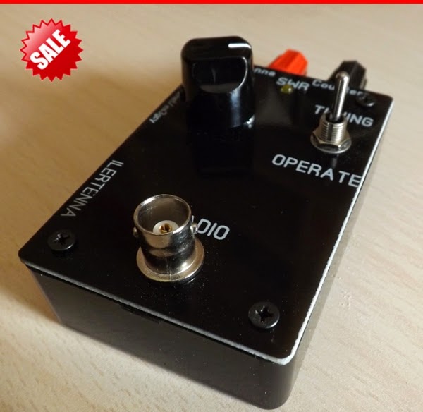 ILERTENNA end-fed QRP antenna tuner single-board design, which overlaps the frequency range 40 - 15M (80 or 17-10M - options) for antennas of the "end-fed" or "zeppelin" type with the transmission intensity up to 5 watts CW 10 watts P.E.P.
Before the pluses of the design, you can add an adjustment indicator on the light diode (in fact, it is absolutely standard for similar designs) and the adjustment of the tuner with only one handle (indeed, within the range of the light, set when folding the design)
Є Assembly Manual with full description and data for self-folding. About every change In the description, there is a picture of the trasuvannyam of the drukovanoї pay, so that at once I will add the upper panel.
In the description there is a plate of other vibrators for different ranges.
Antennas Tunery
ACS. Antenna tuners. Schemes. Look around the branded tuners
In amateur radio practice, it is not often possible to shoot antennas, for some input opir є equal to the feeder's winding support, and wind the transmitting output support.
For most vipadkivs, such viability does not come into play, so it is necessary to win the specialization of antennas of the narrow extension. Antenna, feeder and output transmission (transiver) are included in a single system, energy is transmitted without any cost.
What do you need an antenna tuner for?
Vіd Oleksiya RN6LLV:
At this video, I will tell the radio amateurs about antenna tuners.
An antenna tuner is now needed, as well as competently vikoristovuvat at once with an antenna, and like typical pardons about tuner jamming are found in radio amateurs.
To go about the ready-made virib - tuner (vibration by the company), if it is necessary to encourage the authorities, to spare or to experiment - then you can skip the video and divas. far (below).
Call from the bottom - look at the branded tuners.
Antenna tuner, buy antenna tuner, digital tuner + with antenna, automatic antenna tuner antenna tuner LDG, SW meter
All-range uzgojuvalny attachment (with separate coils)
Replacing condensers and 2-way changeover switch R-104 (BSN unit).
For the number of appointments of capacitors, it is possible to close 2-sections, in the form of radio receivers, by increasing the sections in sequence and insulating the case and the entire capacitor in the chassis.
You can also zastosuvat zvichayny biscuit peremikach, replacing the entire wrapping on dielectric (sklotekstolit).
Details of the tuner coils and accessories:
L-1 2.5 turns, wire AgCu 2 mm, outer coil diameter 18 mm.
L-2 4.5 turns, wire AgCu 2 mm, outer coil diameter 18 mm.
L-3 3.5 turns, wire AgCu 2 mm, outer coil diameter 18 mm.
L-4 4.5 turns, wire AgCu 2 mm, outer coil diameter 18 mm.
L-5 3.5 turns, wire AgCu 2 mm, outer coil diameter 18 mm.
L-6 4.5 turns, wire AgCu 2 mm, outer coil diameter 18 mm.
L-7 5.5 turns, drіt PEV 2.2 mm, outer diameter of the coil 30 mm.
L-8 8.5 turns, drіt PEV 2.2 mm, outer diameter of the coil 30 mm.
L-9 14.5 turns, drіt PEV 2.2 mm, outer diameter of the coil 30 mm.
L-10 14.5 turns, drіt PEV 2.2 mm, outer diameter of the coil 30 mm.
Dzherelo: http://ra1ohx.ru/publ/schemy_radioljubitelju/soglasujushhie_ustrojstva_antennye_tjunery/vsediapazonnoe_su_s_razdelnymi_katushkami/19-1-0-652
Just use the antenna LW - "dovgy drіt"
It was necessary to launch 80 and 40 meters at someone else's booth, I can't get out of the house, and I can't get to the installation of the antenna.
Throwing more than 30 m from the balcony of the third on top of a field tree. From the bottom, sprout through the skin 5 turns, and to the beast through 10 turns. Zibrav on the balcony axis is such the simplest uzgodzhuyuchiy attachment.
On the wall, put the field strength indicator. Having increased the range of 80 m in the QRP mode, to the beast of the cat, we have adjusted our "antenna" to resonance with the maximum reading of the indicator, then we have lowered the output to the minimum of the CVP.
It didn’t take an hour, I didn’t put the biscuits on that. and coils "bіgav" with help crocodiles. The whole European part of Russia, especially at 40 m, told me about such a surrogate. This, obviously, is not the right antenna, but the information will be correct.
RW4CJH info - qrz.ru
Uzgodzhuvalny attachment for low-frequency antennas
Radioamatori, yakі live at the rich top booths, often jam on the low-frequency ranges of the frame antenna.
Such antennas do not require high shanks (they can be stretched between the houses at equal heights), good grounding, for their livelihood you can put a cable, and the stench is less shilling.
In practice, the variant of the frame is in the form of a tricot, because for the suspension it needs a minimum number of points of attachment.
As a rule, more short-haired ones should be able to use such antennas as a rich range, prote in the right way to the edge, and secure the best possible antenna with a feeder on all operating ranges.
Extending more than 10 years vicorous antenna of the Delta type on all bands from 3.5 to 28 MHz. Її osoblinosti - tserozashuvannya at the expanse of that vikoristannya uzgodzhuvalnogo outbuilding.
Two vertices of the antenna are fixed on the level of the dahivs of five overhead buds, the third (rozimknena) - on the balconies of the 3rd top, the wires are introduced into the apartment and connected to the uzgodzhuvalny outbuilding, which connection with the transmission of the cable is quite long.
At tsomu, the perimeter of the antenna frame is close to 84 meters.
The principle diagram of the Uzgodzhuvalny outbuilding is induced by a little right-hander.
Uzgodzhuvalny attachment is made up of a wide-range metering transformer T1 and a P-circuit, fitted with an L1 coil with inputs and capacitors that are connected to it.
One of the options for the transformer T1 is shown in fig. levoruch.
Details. Transformer T1 winding on a ferite ring with a diameter of at least 30 mm with a magnetic penetration of 50-200 (non-critical). The winding is wound one hour with two PEV-2 wires with a diameter of 0.8 - 1.0 mm, the number of turns is 15 - 20.
Coil U-contour with a diameter of 40...45 mm and a dove of 70 mm vikonan with bare or enameled copper wire with a diameter of 2-2.5 mm. The number of turns is 13, the number of turns is 2; 2.5; 3; 6 turns, looking up at the left one behind the scheme of seeing L1. Substructures of capacitors type KPK-1 are assembled on studs, packages of 6 pcs. and may have a capacity of 8 - 30 pF.
Nashtuvannya. In order to fix the uzgodzhuvalny add-on, it is necessary to turn on the SWR meter at the opening of the cable. On the dermal range, the narrowing of the junction is observed to be less SWR for additional built-in capacitors and, if necessary, by selecting the position of the inlet.
Raju in front of the installation of the uzgodzhuvalny annex, I added a new cable and installed the external transmission cascade, connecting it to a new equivalent of transmission. After that, you can install the cable with a narrow extension and complete the installation of the antenna. The band is 80 meters divided into two subbands (CW and SSB). When adjusted, it is easy to reach SWR close to 1 on all ranges.
This system can also be switched on the WARC bands (requires only a choice of inputs) and on 160 m, depending on the number of turns of the coil and the perimeter of the antenna.
The next thing to note is that it is more fair only for a non-intermediately connected antenna to the narrow extension. Obviously, this design is not to replace the "hvilyovy channel" or "flying square" on 14 - 28 MHz, but it's good to work on all bands and know a lot of problems for quiet ones, which vikoristovuvaty one broad-band antenna.
The replacement of capacitors, which are humming, you can stop the KPI, or else you can change the antenna when switching to a lower range. But, even though at home such an option is not handy, then the Polish people have a lot of truths in their minds. Changed the "delta" options for 7 and 14 MHz, I repeatedly stopped when working at the "field". With this, two peaks were creaked on the trees, and the lifeboat was connected to the narrow extension, which lay without a middle on the ground.
At the end, I can say that for work on the air, only a transiver with a ventilatory tension is close to 120 W without a subdued tension, with an antenna described by an antenna on the ranges of 3.5; 7 and 14 MHz are not at all difficult, with which I work, as a rule, on a wild week.
S. Smirnov, (EW7SF)
The design of a simple antenna tuner
Antenna tuner design RZ3GI.
I am promoting a simple version of an antenna tuner, chosen for a T-like circuit.
Tested with FT-897D and IV antenna at 80, 40 m.
Will be on all HF bands.
The coil L1 is wound on a mandrel 40 mm with a crochet of 2 mm and may 35 turns, wired with a diameter of 1.2 - 1.5 mm, leads (including the type of "earth") - 12, 15, 18, 21, 24, 27, 29, 31, 33, 35 vitkiv.
Coil L2 maє 3 turns on a mandrel 25 mm, winding length 25 mm.
Capacitors С1, С2 із С max \u003d 160 pF (for a large UKH station).
SWR meter stays on (for FT - 897D)
Antenna Inverted Vee at 80 and 40 meters - will be on all bands.
Yury Zіborov RZ3GI.
Tuner photo:


"Z-match" antenna tuner
Under the name "Z-match" in the absence of any design and schemes, I would say more designs below the schemes.
The basis of the circuit solution, as I have seen it, is widely expanded in the Internet and offline literature, everything looks something like this (div. right-handed):
І axis, looking at the impersonal schemes, photographs and notes of placement at the edge, I had an idea to choose an antenna tuner for myself.
My hardware magazine was leaning under my hand (so, so, I am an old-school addict - old school, like juveniles appear) and on the other side a scheme of a new device for my radio station was born.
I had a chance to learn the side of the magazine “for getting better”:
It is worth remembering that there may be significant powers in the case of pershogerel. I became zastosovuvat іnductivnu zv'yazok za antena z її symmetrіchnіstyu, less dosit autotransformer circuit tk. It is not planned to live the antennas with a symmetrical line. For the convenience of setting up and controlling the antenna-feeder spores, I added an SWR meter and a wattmeter to the main circuit.
Having finished with the layout of the elements of the scheme, you can proceed to the layout:


The Crimean corps is brought to prepare and operate radio elements, one of the few radio components, so that the radio amator can operate the same inductance coil:
And the axis that resulted in the result is in the middle of that ring:


The scale has not yet been marked, the front panel is faceless and not informative, but the brand is PRATSYU! І tse good ...
R3MAV. info - r3mav.ru
Equal attachment for analogy Alinco EDX-1
Tsya scheme of the antenna uzgozhuvalnogo add-on I have positioned from the branded Alinco EDX-1 HF ANTENNA TUNER, which is a pratsyuvav from my DX-70.
Details:
C1 and C2 300 pf. Capacitors from the case of a dielectric. Croc plates 3mm. Rotor 20 plates. Stator 19. Ale, you can zastosuvat zdvoenі KPI with plastic dielectric in the form of old transistor priymachiv or repeat dielectric 2x12-495 pf. (like a sign)
You ask: “But why aren’t you?”. Right in that the coaxial cable is soldered without a middle to the stator, but at 50 Ohm, can a spark slip through such a low support?
Sufficiently stretch the condenser "barely" with a dart a line of 7-10 cm long, like a fire to burn blue half-lights. To remove static, the capacitors can be shunted with a 15 kOhm 2 W resistor (quote from "Supporting the tension of the UA3AIC design").
L1 - 20 turns of silver dart D=2.0 mm, frameless D=20 mm. Vіdvedennya, rahuyuchi vіd upper for the scheme of kintsya:
L2 25 turns, PEL 1.0, wound on two ferrite rings folded at once, size D outer = 32 mm, D inner = 20 mm.
Tovshchina of one ring = 6 mm.
(For 3.5 MHz).
L3 28 turns, and the same as L2 (For 1.8 MHz).
Alas, it’s a pity, at that hour I didn’t know the proper stumps and made it like this: Vitochiv s orgskla studs and wrapped darts around them until they were full. Subsequently, in succession - ce viyshov equivalent of L2.
On a mandrel with a diameter of 18 mm (it is possible to vicorate a plastic sleeve in the form of a 12-gauge towel), winding up to a turn winding 36 turns - a ceiling analogue of L3.
You can see everything on the sign. І SWR meter also. SWR meter from the description of Tarasov A. UT2FW "HF-VHF" No. 5 for 2003 rec.
Uzgodzhuvalny attachment for antennas delta, square, trapezium
Among the radio amateurs, the popularity of a loop antenna with a perimeter of 84 m is very popular. Such a compromise can be accepted, as if it were practicable for a lamp-like underpressure, but even if it is possible a modern transceiver, there is no way to the right. It is necessary to use an adaptive device, which will set the SWR on the skin band, which is similar to the normal operation of the transiver. HA5AG rozpovіd me for a simple uzgodzhuvalny pristіy and nadіslav me a short yogo description (look at the little ones). Attachments for splitting for loop antennas are practically any shape (delta, square, trapezium, thin)
Short description:
The author's convenient attachment was tested on the antenna, the shape of which mayzhe is square, installed at a height of 13 m in a horizontal position. The input opir of the QUAD antenna on the 80 m band is 85 ohms, and on the harmonics 150 - 180 ohms. Hvilyovy opir to the cable of life 50 Ohm. The manager was to fit the cable with the input support of the antenna 85 - 180 Ohm. For the sake of convenience, the transformer Tr1 and the coil L1 were installed.
At a range of 80 m, behind the auxiliary relay P1, the coil n3 is short-circuited. At the lance cable, it is necessary to turn on the n2 coil, as for its own inductance, put the input support of the antenna at 50 ohms. On other bands, P1 is switched off. The lancet cable includes coils n2 + n3 (6 turns) and the antenna is 180 ohm to 50 ohm.
L1 - cat, what do I move. Vіn know your stasis on the 30 m band. On the right, the third harmonic of the 80 m band does not match with the allowable frequency range of the 30 m band. (3 x 3600 kHz = 10800 kHz). Transformer T1 to fit the antenna at 10500 KHz, but it is still not enough, it is necessary to turn on the L1 coil and in such an included antenna it is already resonant at a frequency of 10100 KHz. For this, after the help of K1, relay P2 is switched on, which opens its normally closed contacts. L1 can also be used in the range of 80 m, if it is necessary to work in the telegraph office. On the 80th smuga band, the antenna resonance is close to 120 kHz. To increase the resonance frequency, you can increase L1. The L1 coil is turned on, which gradually lowers the SWR and on the 24 MHz frequency, as well as on the 10 m band.
Uzgodzhuvalny attachment has three functions:
1. Ensuring the symmetrical livelihood of the antenna, the fragments of the antenna fabric are insulated on the RF output of the "ground" through the coils of the transformer Tr1 and L1.
2. Uzgodzhuє impedance, we will describe in a higher way.

3. Behind the auxiliary coil n2 and n3 of the transformer Tr1, set the resonance of the antenna at the different frequency ranges. About the following report: If the antenna is tuned to the frequency of 3600 kHz (without the inclusion of the uzgodzhuvalny attachment), then on the 40 m band it will resonate at 7200 kHz, on 20 m at 14400 kHz, and on 10 m lower at 28800 kHz. Tse means - the antenna needs to be lowered in the skin range, and if so, the frequency of the band will need to be lowered more. The axis itself is such a twist to make the antenna better. Coils of the transformer n2 and n3, T1 with a singing inductance, more subdued antenna, more frequency range. In this way, on a 40 m band, the coils are held by a small world, and on a 10 m range, even a significant world. Correctly tuned antenna should be placed at the resonance of the skin band near the first 100 KHz frequency.
The positions of the indicators K1 and K2 for the ranges are indicated in the tables (right-handed):
If the input opir of the antenna on the 80 m band is installed not between 80 - 90 ohms, but between 100 - 120 ohms, then the number of turns of the coil n2 of the transformer T1 will need to be increased by 3, and if the opir is more so by 4. without change.
Translation: UT1DA dzherelo - (http://ut1da.narod.ru) HA5AG
SWR meter
On fig. on the right, the principle diagram of the attachment is shown, which includes an SWR meter, for the help of which it is possible to adjust the Cі-Bi antenna, and the narrow attachment, which allows you to bring the opir of the tuned antenna up to Ra \u003d 50 Ohm.
Elements of the SWR meter: T1 - antenna strum transformer, wound on a ferite ring M50VCh2-24 12x5x4 mm. The first winding I is a conductor with an antenna strum, stretched at the ring, the winding II is 20 turns of wire at the plastic insulation, and it is wound evenly along the entire ring. Capacitors C1 and C2 are of the KPK-MN type, SA1 is a toggle switch, RA1 is a 100 μA microammeter, for example, M4248.
Elements of the narrow attachment: coil L1 - 12 turns PEV-2 0.8, inner diameter - 6, dozhina - 18 mm. Capacitor C7 - type KPK-MN, C8 - whether ceramic or mica, operating voltage not less than 50 V (for transmission voltage not more than 10 watts). Remikach SA2 - PG2-5-12P1NV.
To adjust the SWR meter of yoga, turn it off to the narrow circuit (in t. A) and connect it with a 50-ohm resistor (two parallel-connected MLT-2 100 Ohm resistors), and connect a C-Bi radio station to the input, which works on transmission. In the mode of vimiryuvannya direct whil - in the one indicated in fig. 12.39 in the SA1 position - the attachment is to show 70...100 µA. (This is for transmitting 4 W power. If the voltage is too low, then "100" on the PA1 scale is set otherwise: by selecting a resistor, which shunts PA1 with a shorted resistor R5.)
By switching SA1 to a different position (control of the whirlwind), adjusting C2 will increase the zero reading of RA1.
Then the input and output of the SWR meter are changed by the points (the SWR meter is symmetrical) and the procedure is repeated, setting the "zero" position C1.
At the end of the adjustment of the SWR meter, the first turn is connected to the seventh turn of the coil L1.
The SWR of the antenna path is determined by the formula: SWR \u003d (A1 + A2) / (A1-A2), where A1 is the indication of RA1 in the mode of direct wheezing, and A2 is the reverse. I would like to say more here not about SWR, like this, but about the magnitude and nature of the antenna impedance induced to the antenna rose station, about its influence on the active Ra = 50 Ohm.
The antenna path will be improved, as if changing the length of the vibrator, the opposite, sometimes - the length of the feeder, the inductance of the coil, which will change (like it won't) that in. bude otrimaniy minimally possible SWR.
Any inaccuracy in the alignment of the antenna can be compensated for by a disorder in the L1C7C8 circuit. You can use a capacitor C7 or change the inductance circuit - for example, the introduction of L1 of a small carbonyl core.
As it shows the adjustment and adjustment of the C-Bi antennas of different configurations and expansions (0.1 ... 3L), under control and for the help of this accessory, it is not important to take the SWR = 1 ... 1.2 in the range.
Radio, 1996, 11
Simple antenna tuner
To use a transceiver with different antennas, you can successfully install the simplest manual tuner, the circuit of which is shown in the small picture. Vin overlaps the frequency range from 1.8 to 29 MHz. In addition, this tuner can be used as the simplest antenna commutator, which can be equivalent to the interference. The tension, which should be brought to the tuner, lie in the gap between the plates of the capacitor of the variable capacity C1, which zastosovuetsya - the more wines, the better. With a gap of 1.5-2 mm, the tuner vibrated up to 200 W (maybe more - for further experiments, in my tightness, the TRX did not stick out). One of the SWR meters can be turned on at the tuner input for SWR muting, although if the tuner is combined with imported transceivers, it is not obligatory - all stinks can be used for the SWR muting function (SVR). Two (or more) HF sockets type PL259 allow you to connect an antenna, selected for an additional switch S2 "Antenna Switch" for operation with a transceiver. This jumper can be set to “Equivalent”, with which the transceiver can be connected to an equivalent voltage with a support of 50 ohms. For additional relay switching, you can turn on the “Bypass” mode, and the antenna or equivalent (depending on the position of the antenna switch S2) will be directly connected to the transiver.
Yak C1 and C2 are installed with standard KPE-2 with an additional dielectric 2x495 pF in the industrial butt priymachiv. These sections are passed through one plate. C1 task two sections, connected in parallel. Vіn vstanovleny on plate z orgskla zavtovshki 5 mm. C2 has one section. S1 - HF turntable jumper to 6 positions (2H6P trebles from ceramics, their contacts are connected in parallel). S2 - the same, ale three positions (2Н3П, otherwise the position is more fallow due to the number of antenna roses). Coil L2 - wound with a bare medium dart d = 1mm (shorter than silver), total 31 turns, wound with a small croc, outer diameter 18 mm, 9+9+9+4 turns. Coil L1 - tezh, ale 10 turns. Coils are installed mutually perpendicular. L2 can be soldered with frills to the contacts of the biscuit jumper, having zignuvshee the coil with a pivkilz. Installation of the tuner is carried out with short tovstims (d = 1.5-2 mm) with stripes of a bare copper rod. Relay type TKE52PD for R-130M radio stations. Obviously, the best option is to install more high-frequency relays, for example, type REN33. The voltage for the life of the relay is taken from the simplest straightener, selected on the transformer TVK-110L2 and the diode bridge KTs402 (KTs405) or similar to them. The switching of the relay is controlled by the toggle switch S3 "Obkhid" type MT-1 installed on the front panel of the tuner. Lamp La (not obov'yazkova) є іndicator on. It may appear that on the low-frequency ranges C2 is not used. In parallel with C2, it is possible, for an additional relay P3 and toggle switch S4, to connect either another section or additional capacitors (select 50 - 120 pF in the diagram is shown by a dotted line).
As a recommendation, the axles of the KPE are connected with the handles of the carving through the holes of the durite gas hose, which are insulators. For їхної fixation vikoristanі vodoprovіdnі clamps d=6 mm. The tuner is prepared for the body according to the Elektronika-Kontur-80 set. The case is larger than the body, lower for the tuner described in , leave sufficient space for modifications and modifications of this circuit. For example, a low-pass filter at the input, some kind of sizing transformer 1: 4 at the output, mounting an SWR meter and others. For an efficient robotic tuner, one should not forget about good grounding.
A simple tuner for adjusting a symmetrical line
A diagram of a simple tuner is pointed at the little one for the sake of a symmetrical line. As an indicator of the setting of vikoristovuetsya svіtlodiod.
Under the name "Z-match" in the absence of any design and schemes, I would say more designs below the schemes. The basis of the circuit solution, as I have seen it, is widely expanded in the Internet and offline literature, everything looks something like this:І axis, looking at the impersonal schemes, photographs and notes of placement at the edge, I had an idea to choose an antenna tuner for myself. Leaning under my hand was my hardware magazine (so, so, I am a hanger-on of the old school - old school, as young people look) and on the other side a scheme was born of a new device for my radio station. I had a chance to learn the side of the magazine “for getting better”:

It is worth remembering that there may be significant powers in the case of pershogerel. I became zastosovuvat іnductivnu zv'yazok za antena z її symmetrіchnіstyu, less dosit autotransformer circuit tk. It is not planned to live the antennas with a symmetrical line. For the convenience of setting up and controlling the antenna-feeder spores, I added an SWR meter and a wattmeter to the main circuit.
Having finished with the layout of the elements of the scheme, you can proceed to the layout:


The Crimean corps is brought to prepare and operate radio elements, one of the few radio components, so that the radio amator can operate the same inductance coil:

And the axis that resulted in the result is in the middle of that ring:


The scale has not yet been marked, the front panel is faceless and not informative, but the brand is PRATSYU! І tse good ...
R3MAV
info - r3mav.ru
Under the name "Z-match" in the absence of any design and schemes, I would say more designs below the schemes. The basis of the circuit solution, as I have seen it, is widely expanded in the Internet and offline literature, everything looks something like this:
І axis, looking at the impersonal schemes, photographs and notes of placement at the edge, I had an idea to choose an antenna tuner for myself. My hardware magazine leaned under my arm (so, so, I’m a hanger-on of the old school - old school, as young people look) and on the other side a scheme of a new device for my radio station was born. I had a chance to learn the side of the magazine “for getting better”:
It is worth remembering that there may be significant powers in the case of pershogerel. I became zastosovuvat іnductivnu zv'yazok za antena z її symmetrіchnіstyu, less dosit autotransformer circuit tk. It is not planned to live the antennas with a symmetrical line. For the convenience of setting up and controlling the antenna-feeder spores, I added an SWR meter and a wattmeter to the main circuit.
Having finished with the layout of the elements of the scheme, you can proceed to the layout:


The Crimean corps is brought to prepare and operate radio elements, one of the few radio components, so that the radio amator can operate the same inductance coil:


