Pushing that yakіsny self-robbed pіdsilyuvach sound. Simple timbre blocks on transistors and on OU (KT3102, K140UD8) Schematic diagram of a timbre block for a car driver
Subwoofer low pass filter
The low-frequency acoustic system sounds cumbersome and expensive, and taking into account those that people's hearing cannot recognize stereo at low frequencies, it became clear that there is no sensation in two low-frequency speakers - one each for the skin stereo channel. Particularly as a practical application is a stereo system of a small size.
In such a mode, it is necessary to subsume the signals of stereo channels, and then to see the low-frequency signal from the removed signal. Small 1 shows a diagram of an active filter, which is connected to two operating sub-circuits of the microcircuit TL062.
Stereo channel signals should be on X1 socket. Resistors R1 and R2 are combined with the inverted input of the op-amp A1.1 to create a mixer that forms a solid mono signal for the stereo signal, op-amp A1.1 ensures the necessary amplification (or attenuation) of the input signal. The level of the signal is regulated by a changeable resistor R3, which is to enter the warehouse of the OOC A1.1. From output A1.1, the signal should go to LPF A1.2. The frequency can be regulated by a double changeable resistor, which is added from R7 and R8.
The low-frequency signal to the low-frequency ULF or the active low-frequency speaker goes through the X2 jack.
Zhivlennya - bipolar, go through the X3 rose, it is possible to enter ± 5V to ± 15V.
Mixer for robots and triplets with microphones.
Якщо потрібно сигнали від трьох окремих джерел, наприклад, від мікрофонів подати на один вхід записуючого або відтворювального аудіопристрою, потрібен мікшер, за допомогою якого можна об'єднати аудіосигнали від трьох джерел в одне, і відрегулювати їх співвідношення за рівнями так, як це потрібно.

Small 2 shows a mixer, splitting on a microcircuit type LM348, in yakіy є chotiri operating pіdsilyuvachi.
The signals from the microphones are given directly to the sockets X1, X2 and X3. Far, on the microphone anterior pads on operational subsidiaries A1.1, A 1.2 and A1.3. p align="justify"> Coefficient of skin OC strength to lie down according to the parameters of the 1st lance of the OOS. Tse allows you to adjust the coefficient of strength in wide ranges by changing the support of resistors R4, R10 and R17 is clear. To that, as in the capacity of one or the other dekіlkoh the signal would not be victorious, not a microphone, but an attachment with a higher equal output voltage of the AF, you can use the coefficient of strength of the power supply op-amp to install the support of the power resistor. Moreover, the range of setting the coefficient of strength is even greater - from hundreds and thousands to one.
Stronger signals from three dzherel need to be changed by resistors R5, R11, R19, for the help of which you can quickly adjust the speed of signals a wild signal until the signal is completely strangled from one or the other dekilkoh dzherel.
Vlasne, mixer of vicons at OS A1.4. The signals from this inverted input must come from the change resistors through the resistors R6, R12, R19.
The low-frequency signal to the external recording or substation is to be reached through the X5 socket.
Zhivlennya - bipolar, come through the X4 rose, it is possible from + 5V to + 15V.
The scheme can be chosen whether there are some operational subdivisions of a criminal confession.
Front podsiluvach with timbral block.
A lot of radioamators will be UMZCH on the basis of UMZCH microcircuits-integrated circuits, sounding signs for automotive audio equipment. The main thing is that the whole UMZCH has the shortest term and the minimum labor costs. It’s not enough for the fact that the ULF does not come out again, without podsilyuvacha with the regulation of the volume and timbre.

A circuit of a simple switch with a loudness and timbre control, based on the widest elemental base - transistors KT3102E, At the pіdsilyuvach to finish the great entrance opіr, schob vіn the moment pratsyuvati practi- cally s be a kind of signal, sound card A PC and a digital player, to an archaic vinyl disk player with a p'zoelectric pickup head.
The cascade on transistors VT1 of impulses behind the circuit of the emitter repeater and serve, mainly, for moving the input support and lowering the inflow of parameters to the output of the signal to control the tone.
The frequency regulator is a change resistor R3, and at the same time it is the change of the emitter repeater on the transistor VT1.
Dali - passive bridge tone control for low and high frequencies, looping on change resistors
R6 (low frequencies) and R10 (high frequencies). Adjustment range 12dB.
The cascade on transistors VT2 serves as a compensation for losses equal to the signal to the passive tone control. The strength coefficient of the cascade on VT2 is to lie in the great world according to the magnitude of the OOS, without intermediary support of the resistor R13 (less, then the strength coefficient fits more). Mode by fast strum installed by resistor R11 for the cascade on VT2 and R1 for the cascade on VT1.
A stereophonic version can be formed from two such subs. Resistors R6 and R10 are due to double, so that the timbre can be adjusted simultaneously in both channels. Thickness regulators can be applied to the skin canal.
The voltage of life is 12V, unipolar, it corresponds to the rated voltage of life of more microcircuits - integrated UMZCH, insurance for work in automotive technology.
Radio adapter
All stationary audio equipment can be divided into line output and line input. You can send a signal to the line input hello dzherel, in order to vikoristovuvaty the main device yak pіdsilyuvach with acoustic systems or for recording, in large portable equipment there is simply no line input. Unite "by means of communication with zvishnіshnіm svіtom» є a microphone and a radio receiver. One of my friends tried to rewrite the signal from the MP-3 flash player on a magnetic cassette, putting on headphones on the microphone "dirochka" of an old portable CD-recorder. Wiishlo greedily. If you want to be able to use the FM receiver quickly, you may also need the simplest adapter for it.
For sound transmission to a stereo signal, you can use a purchased FM modulator, assignments for dartless connection to the car radio of the sound signal. The new one has a stereo modulator, a good frequency synthesizer transmits and, often, the MP-3 player is connected to an external flash drive or a memory card. Well, in the simplest way, you can build a primitive single-transistor low pressure gear, The signal of which receiver can be received when the transmission is close to the second antenna.
The adapter diagram is shown in figure 4.

The circuit is a cascade of a high-frequency generator on transistors VT1, which works for high-frequency for a circuit from a base base, the base lance of which a modulating low-frequency signal is supplied.
Signal sonic frequency from the outside dzherel go to the base VT1 through the capacitor C4 and two resistors R1 and R2, which serve as a stereo channel mixer. So, the circuit is quite simple and there are no other nodes in it, which form a complex stereo signal, at the input, receiving a signal for a monophonic look.
Low-frequency voltage, nahodyachi z urahuvannyam transistor VT1, zmіnyuє yak yogo working point, and єmnіst transition. As a result, the amplitude-frequency modulation is changed. Amplitude modulation is effectively accommodated in the receiving radio path, and frequency modulation is detected by a frequency detector.
The HF frequency, which is to be broadcast, is set by the L1-C2 circuit. In fact, there is no antenna - the adapter is placed in the direct vicinity of the receiving antenna, and the signal on it comes directly from the contour coil.
Contour coil L1 - frameless, її inner diameter 10-12 mm, wound with a wire PEV 1.06, 10 turns in total. It is possible to fix the circuit as if it were a built-in condenser, as well as to tighten the windings of the coil.
Life - two elements of 1.5V (3V).
Equity indicator.
For the correct installation of the stereo balance and the prevention of ULF re-tuning and acoustic systems bazhano, schob at the warehouse ULF buv indicator is equal to the signal, which should be at the entrance of the ULF.
From a practical point of view, for independent preparation, the best indicator based on the light scale, vin and mechanically significant for the small scale and simple and cheap for the scale mnemonometric.
Small 5 shows a diagram of an indicator for offending stereo channels. Winning on the basis of a microcircuit TA7666R.
In the middle of the IMS TA7666R there are two subilluminators with detectors at the outputs and two lines of comparators, five comparators for the skin channel.

Coefficient of strength of skin protection can be installed individually by selecting the support of resistors R1 and R2. When the value is indicated on the diagram, the first stage of the light diodes (НL1 and HL6) will sleep at input levels of 48 mV, the other stage (HL2, HL7) at 86 mV, the third stage (HL3, HL8) at 152 mV, the fourth stage (HL4, HL9) at 215 mV, pins (HL5, HL10) for 304 mV. The way of displaying the indication is "Bag", that is "the thermometer's stand", otherwise it seems, the larger the signal, the more the line of light, which shines.
You can change the sensitivity by selecting the support resistors R1 and R2.
On the basis of this microcircuit, you can create your own light-dynamic attachment, for example, stacks of concentric kil lamps for heating or light lamps, for example, to get stuck in car optics. Which one will need additional exhaust cascades.
Figure 6 shows a diagram of an output cascade for working on car LED lamps. An optocoupler with a phototransistor U1 is switched, and a light diode is connected to the replacement of the indicator light.
HF1 - no car light one lamp. Vaughn is hard and for її switching polovy transistor VT1.
Grinov V.A.
Moving bugs R2 and R6, marveling at the changes that are angry. The program already has a ready-made variant of the timbre, you may not be able to win (meni, for example, ni) - Bachimo, that the midbass (80-400Hz) possible reason hum, resonance in the audience, that for a comfortable listening to music and frequencies are not to blame. Another reason why the tone block may not be suitable is the presence of replacement resistors in the required nominal value. I like the timbre of the pidsiluvach Trembita-002-stereo(Issue of 1977) and, let's say, want to bi-yogo polypshit and modernize. Press Snapshot to visually change:

Such a variant of the timbre is less to the soul, but weakens the signal of the wines a little stronger - not bad - then the midbass is not stronger when the resistor R2 is fully twisted. With a further selection of elements, such an option will come out - accepting my idea for listening:

The frequency of 1kHz is left practically untouched, but at 2kHz and the frequencies are more raised at the same time as the carrier 18kHz - the quality factor has increased. To whom it should be, but in equalizers, de smug rich - the work quality is less, so for example, with a 1kHz boost, 500Hz and 2kHz sound, they saw a small pidyom - otherwise there will be no sense in such an equalizer. For such a scheme, for lowering the quality factor, there are additionally two resistors and the circuit looks like this:

But still not all. After folding such a timbre block, you will notice a stronger decrease in volume - so it is, passive regulators greatly reduce power. Sound to add one more cascade, for example, to the OS - it’s simpler, those parameters become very stale in the form of an operational booster, you can at some point replace it with a smaller one, and, perhaps, you will receive a boost. Sound the timbre, turn on the Lanciug zvorotny zv'azku podsilyuvalny cascade, like, for example, Shmelov's podsilyuvachi. I hacked like this:

Capacitors whether K73-9, K73-17, MBM, BM-2, but not ceramic (remain vikoristovuvaty in lancets correction OU and C6 at the return link). In my own version, unfortunately, I don’t know a 2200p condenser, but on the sound, it didn’t seem right, luckily! .
Discuss the article PASSIVE TONE
Not long ago, I turned like a man from the past to my brother and I have a sufficient tightness and strength in separate channels at low, medium and high frequencies. Before that, more than once, having chosen your own experiment, I must say that the experiments were far away. The sound quality of low-cost speakers is no more than a high level, but it is noticeable when it is improved in equal parts, for example, with the option of blocking passive filters at the speakers. Until then, it becomes possible to easily change the frequency of the distribution of smug and the coefficient of skin strength of the taken smug and, in this way, it is easier to reach the equal frequency response of the entire sound-amplifying tract. At the subsidiaries, there were ready-made schemes, as earlier they were tested in more simple designs.
Structural diagram
The little one below shows the diagram for channel 1:

As you can see from the diagrams, there can be three inputs, one of which transmits a simple possibility of adding a pre-amplifier-corrector for playing the vinyl (for such a need), an input switch, a front bass-timbral lock (also trismogov, with regulation of HF / HF), thickness regulator, block of filters for three smugs with regulation of the level of skin smog strength with the possibility of switching on filtering, and a block of life for the end of the subsidiaries of great tension (unstabilizations) and a stabilizer for the "weak" part of the blue (front cascades).
Front podsiluvach-tone block
As a new scheme, it was repeatedly revised earlier, as for its simplicity and availability of details, it shows good characteristics. The scheme (like and all advances) was published in its time in the Radio magazine and then repeatedly published on various sites on the Internet:
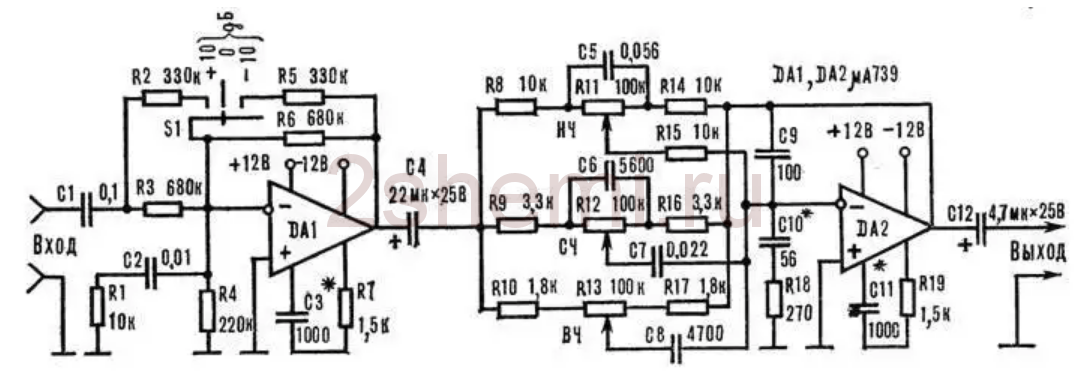
The input cascade on DA1 is to compensate for the change in the level of gain (-10; 0; +10 dB), which will simplify the use of the entire signal booster with different signals, but in DA2 the tone control is selected without a middle. The scheme does not come close to a certain number of denominations of elements and ensures no taxation. Like an op amp, you can zastosuvat whether or not microcircuits that zastosovutsya in the audio paths of subsidiaries, for example here (and in the upcoming schemes) by trying imports BA4558, TL072 and LM2904. Pіdіyde be-yak, ale better, zvichayno, choose the options for the op-amp with possibly less equal damp noise and high swidcode (coefficient of increase in input voltage). Qi parameters can be looked over in dovidniks (datasheets). Obviously, here we need not obov'yazkovo zastosovuvat the scheme itself, as a whole it is possible, for example, to work a trismooth, but a primary (standard) two-smooth timbral block. Ale, I’m not “passive” to the circuit, but with cascades of strength-enhancement, it allows input and output on chi op-amp transistors.
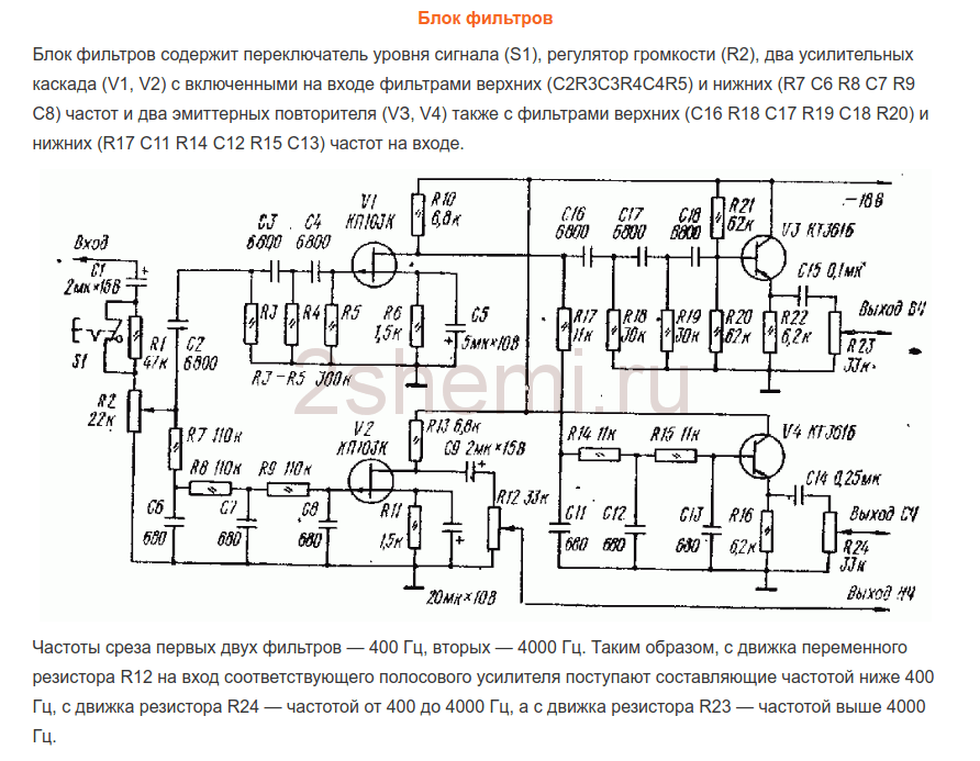
Block of filters
Schemes of filters, also, for a bazhannya you can know without a person, for those who have enough publications on the topic of rich-smoking pidsiluvachiv infections. To ease this task and just for the butt, I’ll bring here a few possible schemes found in different dzherelakh:
- the scheme, as I put it in my podsiluvachi, so as the frequencies of the distribution of the smog appeared the same, as the “castleman” needed - 500 Hz and 5 kHz and nothing happened to overshoot.

- Another scheme, simpler on the OS.
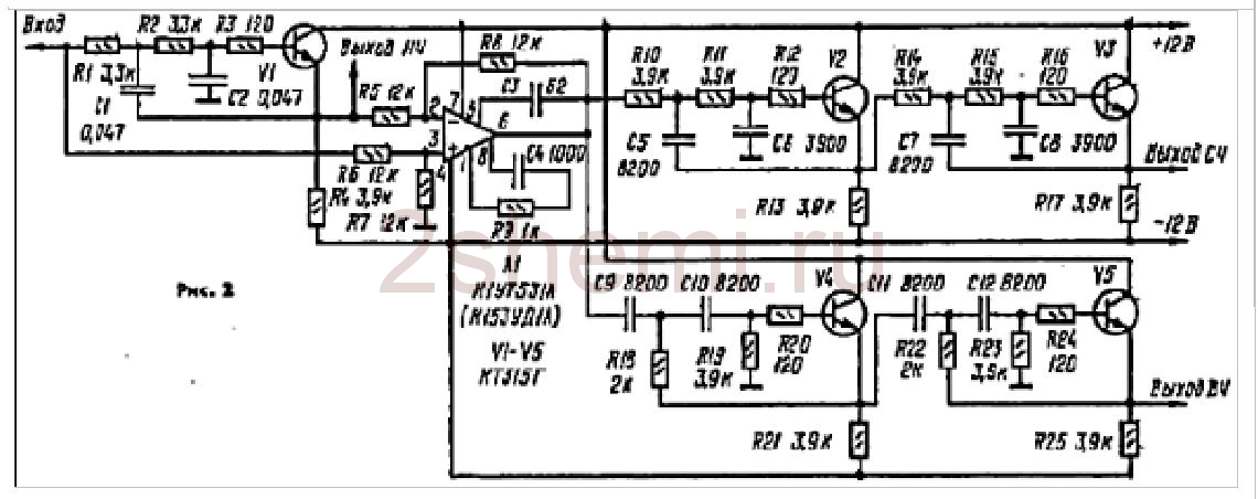
І one more circuit is possible, on transistors:
As already writing yours, having chosen the first scheme through dosit akіsnu filtratsіyu smoog and vidpovіdnіst frequencies podіlu smug we will set. Only at the exits of the skin channel (smuha) were added simple regulators of equal strength (as it is broken, for example, in the third scheme, on transistors). Regulators can be installed from 30 to 100 kOhm. Operational subsidiaries that transistors in all circuits can be replaced with modern imports (with improved pinouts!) to remove the best parameters of circuits. None of the settings of all circuits will be affected, so it is not necessary to change the frequency of the distribution of smog. Unfortunately, I don’t have the ability to give information about how to change these frequencies, because the schemes were joked for the butt “ready” and report descriptions did not reach them.
The scheme for the filter block (the first scheme of three) was given the possibility of switching on filtering by the midrange and high-frequency channels. For this boule, two push-button jumpers of the P2K type are installed, for the help of which it is simply possible to close the entry points of the filter inputs - R10C9 with their own input outputs - "high-frequency output" and "mid-range output". At this vipadku tsimi channels go povny sound signal.
Pіdsylyuvachi
From the exit of the skin channel of the filter, the HF-MF-LF signals are sent to the inputs of the intensification of pressure, which can also be selected according to whether it is from the other schemes in the presence of the necessary tension of the entire induction. I tried UMZCH for a long time to introduce the scheme to the magazine "Radio", No. 3, 1991, p.51. Here I give a plea for “pershodzherelo”, to the fact that the drive of the scheme has a lot of thoughts and a super-chek to її “yakіsnostі”. On the right, in the fact that, at first glance, the scheme subsumes the class "B" with the inevitable presence of the "gathering" type, but not so. The scheme has a strum control of the transistors of the output cascade, which allows these short circuits to occur when the standard is switched on. In this case, the circuit is even simpler, not critical to zastosovuvanih details and turn on the transistors do not have a special forward selection for the parameters. output”, which I will also ask for the installation of a pilot:

If you have installed it, it is IMPORTANT to select the correct modes of operation of the transistors in the front-end cascade (selection of resistors R7R8) - on the bases of these transistors in the "calm" mode and without navantage on the output (dynamics), there may be a voltage in the range of 0.4-0.6 volts. The voltage of life for such power supplies (їх, power supply, may be 6 pieces) is increased to 32 volts by replacing the output transistors with 2SA1943 and 2SC5200, the opir resistor R10R12, with this, also increase up to 1.5 kOhm OU). The op-amp was also replaced by VA4558, with which the “zero-setting” lancet is not needed (see 2 and 6 on the diagram) and the pinout changes when the microcircuit is soldered. As a result, after an hour of re-checking the leather, the pilot for the scheme saw tension up to 150 watts (short-hourly) with an adequate heating stage of the radiator.
ULF living block
As a block of life, there were two transformers with blocks of rectifiers and filters for a sizable, standard circuit. For living low-frequency smug channels (left and right channels) - a transformer with an intensity of 250 watts, vipryamlyach on diode folds of the MBR2560 type or similar capacitors 40,000 microfarads x 50 volts at the skin shoulder of the living. For midrange and HF channels - a transformer with a voltage of 350 watts (taken from a burned-out Yamaha receiver), a straightener - a folding diode TS6P06G and a filter - two capacitors of 25,000 microfarads x 63 volts on the skin shoulder of the living room. All electrical filter capacitors are shunted with fused capacitors with a capacity of 1 microfarad x 63 volts.
Zagalom, the block of life can be with one transformer, obviously, but for some kind of tightness. The pressure of the patient in general to this particular type vyznayetsya exclusively by the possibilities of life. Use of the front power supply (tone block, filter) - power supply also from one of these transformers (you can use any of them), and also through the additional block of a bipolar stabilizer, selections for MC type KREN (or import ones) typical schemes on transistors.
Construction of a self-propelled pidsiluvach
Tse, perhaps, the most convenient moment in the preparation, to that, there was no known ready-made case and happened to be able to choose possible options :-)) like this:

All the “stuffings” were, naturally, twisted and the layout came out approximately the same (sorry for not taking a photo):

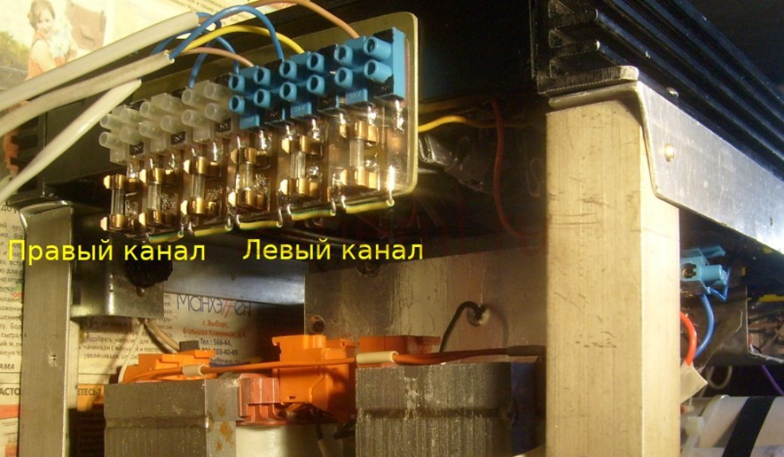
- maybe, six boards of the end UMZCH and the board of the front podsiluvach-timbral block were installed at the radiator cap. The board for the filter unit didn’t fit anymore, it was fixed on an additional structure with an aluminum wrap (you can see it on the little ones). Also, transformers were installed in this "framework", which rectified and filtered the living blocks.
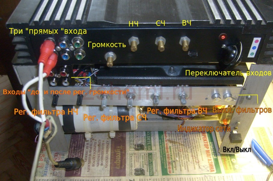
Looking (from the front) with switches and regulators like this:
Rear view, with output pads to the speakers and a block of guards (the shards of the electronic circuitry did not fight through the marriage of space in the design and so as not to complicate the circuit):
Nadal the frame from the cove is transferred, obviously, close it with decorative panels for a more “commodity” look, but you’ll be more robust than the “deputy man” himself, for his own special taste. And in the dark, for the brightness and intensity of the sound, the construction turned out to be quite decent. Author of the material: Andriy Barishev (specially for the site website).
Listen to how it sounds like class D on the IRS2092. After the unfortunate
Poshukіv on Ali, the spell was broken. For the sake of the interest “how it sounds like it” for the new bov and the timbre block.
Oscilki pіdsilyuvach shche in dorozі, and timbral block vzhe priyshov, then virіshiv.
zrobiti looking around for the time being at the new one. As soon as the pidsiluvach comes, I look around and look at
new іz vimirami.
The payment came in an envelope with puhirt. The kit includes the circuit itself
Chotiri knobs on resistors. Flux veze vіdmito soldering more less
neat. Divorce pay average. Regulators in the photo - zlіva to the right - HF, MF, LF, Guchnist.

OP NE5532P is installed on the board 
Also, on the plate of roztashovanі lancets of stabilization of life (L7812 and L7912) that vipryamlyach.
It is possible to supply a change of voltage from the transformer for living
pay.
Schematic diagram regulator similar to qiu 
The ratings of the current resistors and the number of days of the current ones are changed
capacitors.
Now nagolovnіshe - tests.
Testing on my card 
Creative Sound Blaster X-Fi Titanium PRO with a small fee - I will be responsible for shielding the back panel of the other board, replacing the output op-amp with OPA2134, all the life capacitors are shunted with ceramics.
AFC (with erysipelas color - from the entrance to the exit min timbral block, blue color
- through the tone block - all tone controls in the middle position) 
You can see a small peak at low frequencies (below 200 Hz) and a blockage at
high (higher than 6kHz)
Bass controls at extreme positions 
Midrange controls at extreme positions 
Treble controls at extreme positions 
KND "THD", the right channel goes through the tone block for matching (from the output of the card to
input), KHI to the tone block 0.016%, I would like it to be less loudly. Having tried to put OPA2134 in place of other op amps, the trochs decreased slightly, but for everything through the wrong payment. 
The influence of the KND in the frequency (the right channel, passing through the tone
erysipelas color on graphics) 
The tone block does not invert the phase of the signal (the right channel goes through the tone block,
erysipelas color on graphics) 
To finish the middle block for the yakistyu, for home-made virobiv pіde yakshko vlashtovuє KNI.
I’m unlikely to put in planning the strength I’ll be through the temples
harmony creations. I'm raising the board myself, and I'm choosing a tone block.
I agree, the information was correct.
At rich modern audio systems, whether it be a music center, a home cinema or a portable speaker for the phone - an equalizer, otherwise, it seems otherwise, a timbral block. With help, you can adjust the frequency response of the signal, tobto. change the number of high and low frequencies in the signal. The timbral blocks are active, most often used on microcircuits. The stench will detract from the obviousness of life, but will not weaken the signal. The second variety of timbreblocks is passive, the stench slightly weakens the high level of the signal, but then does not detract from the liveliness and does not add additional effects to the signal. For the same reason, high-fidelity sound equipment often has the most passive timbral blocks. At the article, it is clear, like a simple 2-smooth timbre block. Yogo can be taken with a self-confident pidsiluvach, otherwise you can win like an okremy attachment.
The scheme of the tone block

Scheme to replace only passive elements (capacitors, resistors). Two changeable resistors serve to regulate the level of high and low frequencies. Capacitors are supposed to zastosuvat plіvkovі, however, as there are no such ones under the hand, they can also be ceramic. It is necessary to choose a skin channel for one such scheme, and in order to make the regulation the same in both channels, it is necessary to double the change resistors. Drukovana fee, vykladena at tsіy statti, vengeance tsyu scheme in podvіyny primirnik, tobto. maє vkhіd i pіd lіviy, i right channel.

Request a fee:
(advantage: 742)
Tone block prepared
The circuit has no active components, so it can be easily soldered by overhead mounting directly on the replacement resistors. Yakshcho є bazhannya - you can solder the circuit other payment like I've grown. Dekіlka photos of the process:


After choosing, you can rewrite the scheme for the robot. A signal is sent to the input, for example, from the player, computer or telephone, the output of the circuit is connected to the input of the switch. Turning changeable resistors you can adjust the level of low i high frequencies at the signal. Do not be surprised, as in the extreme positions the sound will not be narrower - the signal will be weakened again low frequencies, otherwise, navpaki, zavischenimi, it is unlikely that you will be accepted by ear. For the help of the timbral block, you can compensate for the uneven frequency response of the loudspeaker or the speakers, making the sound better for your taste.


